en
Robert Bosch GmbH1 689 979 848 (2005-06-14)
16 BSL 2470
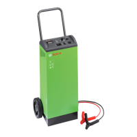
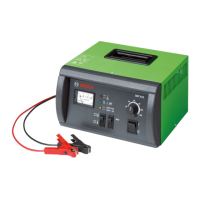
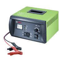
2.4 Note on device symbols
Red LED (Fig. 2, Pos. 2)
Mains display (continuous light)
For reverse polarity or excess externally-sup-
plied voltage to batterycrocodile clips (LED
flashes)
Green LED (Fig. 2, Pos. 3)
„Maximum charge reached“ display
Yellow LED (Fig. 2, Pos. 4)
Charging process underway display (conti-
nuous light)
Battery under-voltage display (LED flashes)
If the yellow and green LEDs do not light up,
the battery voltage is below 1 V (12 V battery)
or below 2 V (24 V battery). Battery charging
does not take place in this condition, because
the polarity of the battery connections cannot
be checked.
Two-way switch for battery temperature
(Fig. 2, Pos. 6)
Battery temperature hot (> 15 °C)
Battery temperature cold (< 15 °C)
Under-voltage button for exhaustive di
-
scharge batteries (Fig. 2, Pos. 7)
Where battery voltages are between 1 V and
8 V in 12 V mode or between 2 V and 16 V in
24 V mode, the under-voltage button has to
be used to start the charging process.
!
..2. Product description
Recommended potentiometer settings when
charge process underway (Fig. 2, Pos. 8)
Pointer on potentiometer button horizontal
facing left: approx. 36 Ah battery.
Pointer on potentiometer button vertical fa
-
cing above: approx. 100 Ah battery.
Pointer on potentiometer button horizontal
facing right: approx. 230 Ah battery.
2.5 Decommissioning
Please dispose of used electronic equipment
-
via the designated recovery systems.
 Loading...