30 en | Configuration
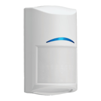
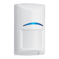
Commercial Series TriTech and TriTech AM
detectors
2022.01 | 01 | F.01U.401.708
Installation manual
Bosch Security Systems B.V.
7 Configuration
Before placing the detector body on the base, and before performing a walk test, configure
the features and options located on the detector body.
7.1 Look-down zone
The detector has a manual cam to enable or disable the look-down zone. Enable the look-
down zone to detect motion under the detector area.
To reduce false alarms, disable the look-down lens for locations where small animals are likely
to cross the look-down zone.
Turn left to disable the look-down zone. Turn right to enable the look-down zone.
7.2 Remote LED
Notice!
Remote LED Input Terminal and Dip Switch
This option is for the TriTech AM model only.
The RLED Dip Switch selection terminal input is a circuit that detects potential differences in
voltage to change the behavior of the walk test LED functions. The RLED input is intended to
allow enabling and disabling the walk test LED functionality without opening the detector
locally. To change the status of the LED, the input requires signal ground voltage potential
(often referred to as “-“, COM, 0 V, or as a COMMON point on the power source) to be
applied. The change resulting by connecting signal ground to the RLED terminal also depends
on how the RLED and LED switch are set. Refer to the table below for proper configuration to
enable/disable the LED remotely