Do you have a question about the Bosch ISC-CDL1-W15G and is the answer not in the manual?
Covers copyright and trademark notices for the document and product names.
Guidance on locating product manufacturing dates using serial numbers and the Bosch website.
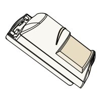
Instructions for using the self-locking cam lock to open, secure, and mount the motion detector base.
Details on mounting the detector on a base, wall, corner, or using various compatible brackets.
Information on selecting and using appropriate wire knockouts for different installation scenarios.
Instructions on utilizing the integrated bubble level for accurate vertical alignment during mounting.
Details the terminal strip, input power, alarm, and tamper connections for the motion detector.
Explains the function of built-in EOL resistors for simplifying wiring and matching control panel loop resistance.
Guidance on using external or built-in resistors for alarm and tamper outputs with different loop configurations.
Specifics on setting up single EOL loops for alarm and tamper, detailing jumper use and resistance values.
Specifics on setting up double EOL loops for alarm and tamper, detailing jumper use and resistance values.
How to enable or disable the look-down zone using a manual cam for sensor area detection.
Explanation of the walk test LED's status indications for various detector conditions like warm-up or fault.
Instructions on conducting a walk test, including LED status and automatic brightness adjustments.
Steps for establishing the detector's coverage pattern by walking through the area and observing the LED.
How to fine-tune PIR and microwave coverage using potentiometers and walk testing procedures.
Details on selecting between high and low PIR sensitivity modes using switch 2 for optimal performance.
Instructions on adjusting microwave sensitivity with a potentiometer to manage false alarms or room size.
Information on the detector's automatic self-test, fault indication, and trouble output activation.
Diagnosing and resolving issues where the detector fails to respond to motion, checking power and wiring.
Identifying causes for the detector remaining in a continuous alarm state, including mounting and power.
Troubleshooting why the detector appears normal but does not send alarms, focusing on loop resistance and wiring.
Resolving issues where motion is not detected directly under the sensor, likely due to the look-down zone.
Troubleshooting weak detection at the coverage area edges, possibly due to microwave range or PIR sensitivity.
Resolving detection failures in the farther sections of the coverage area, often related to range or sensitivity.
Causes for the detector's LED flashing continuously, including warm-up mode and potential unit defects.
Indicates a self-test failure, meaning the detector cannot perform as expected.
Signifies a low supply voltage condition, requiring attention to power source.
Defines the protected coverage area where microwave and PIR patterns overlap, including visual zone indicators.
| Pet Immunity | Up to 25 kg |
|---|---|
| Operating Temperature | -10 °C to +50 °C |
| Color | White |
| Detection Range | 15 meters |
| Detection Technology | Passive Infrared |
| Battery Life | Up to 5 years |
| Power Supply | Battery |
| Tamper Output | Normally closed (NC) |
| Humidity | Up to 95% relative humidity, non-condensing |
| Weight | 150 grams |