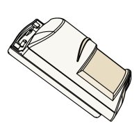
Figure 6.4: Tamper resistors overview
EOL resistor loop combinations
Notice!
When wiring the motion detector, use either external resistors wired into the terminals, or
the built-in resistors for the same output. Do not use both.
Single EOL loop — Alarm and Tamper
Figure 6.5: Single EOL Loop
Callout ᅳ Description
1 ᅳ 1 kΩ
2 ᅳ 2.2 kΩ
3 ᅳ 33 kΩ
6.3
6.3.1
Commercial Series TriTech Motion
Detector
Wiring | en 19
Bosch Security Systems, Inc Reference Guide 2015.06 | 02 | F.01U.314.294