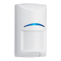
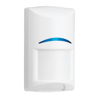
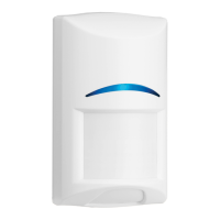
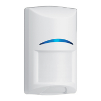
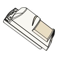
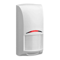
Figure 6.1: Terminal strip overview
Callout — Description
1 — Input power terminals. Voltage limits are 9 to 15 VDC. Use no smaller than 0.4 mm (26
AWG) wire pair between the motion detector and the power source.
2 — Alarm terminals. Solid State output. Use these terminals for Normally Closed relay rated
at 25 VDC, 100 mA, 2.5 W. Do not use with capacitive or inductive loads.
3 — Tamper terminals. Tamper contacts rated at 28 VDC, 125 mA.
Input power terminals
Input power must use only an approved limited power source.
Alarm terminals
– Normally closed solid state voltage-free (dry contact) relay. The contacts are closed
(shorted) during the warm-up period and during normal operation when no alarm is
detected, or if only one technology (PIR or Microwave) is active.
– The alarm contacts change to open status under the following conditions:
– Insufficient input power
– Motion alarm condition (both PIR and microwave activity)
Notice!
When using the built-in resistors between the alarm terminals, there is a resistance value
instead of an open circuit. Jumper selection determines the resistance value.
Tamper terminals
– Normally closed voltage-free (dry contact) switch. The tamper terminals change to an
open state if the motion detector is separated from the mounting base.
6
6.1
16 en | Wiring
Commercial Series TriTech Motion
Detector
2015.06 | 02 | F.01U.314.294 Reference Guide Bosch Security Systems, Inc
 Loading...
