Climate 5000 8736862495(2015/07)
Unit installation | 11
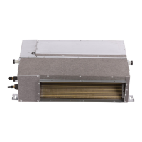
3.5 Installation and connection of steam
coil pipe
Working pressure of steam coil shall not be ex-
cessive, wherein the steam inlet and outlet pipe is
connected through pipe thread or flange, and the
connection type of steam inlet pipe is up-in and
down-out(→Fig. 13-1, 2).
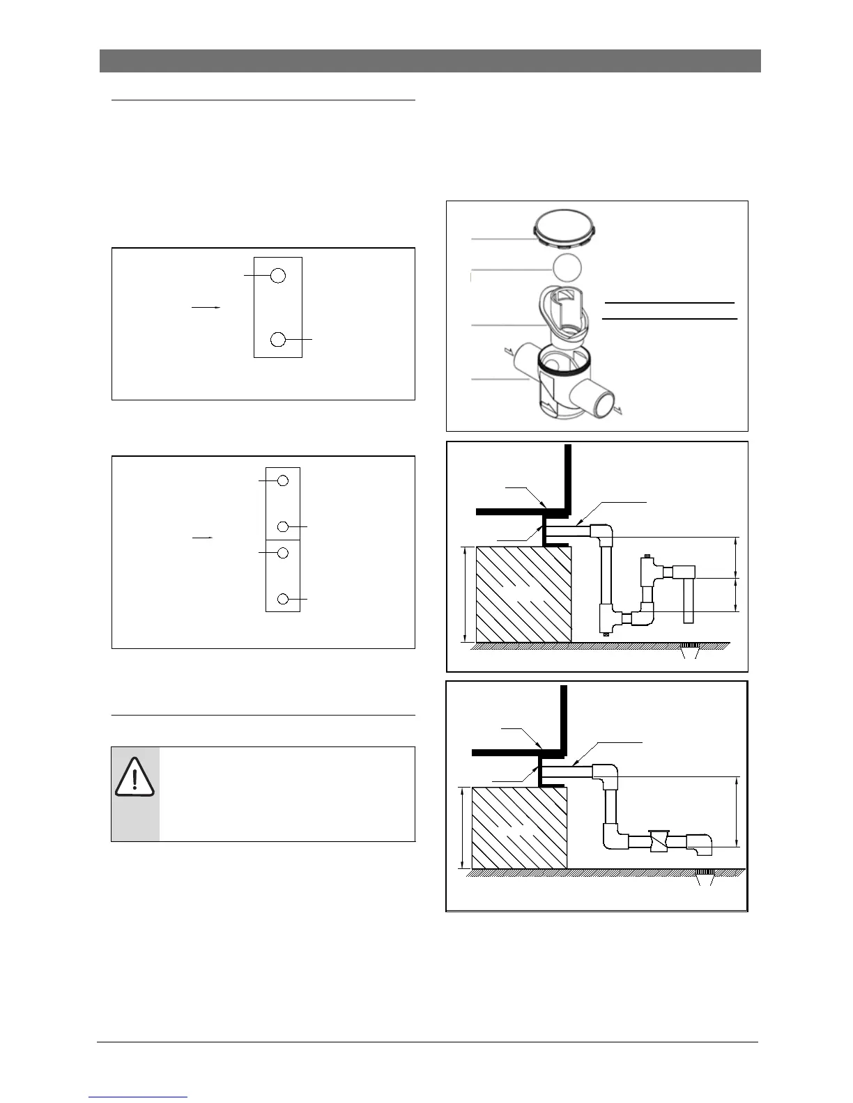
Fig. 13-1 Schematic diagram of inlet and outlet
pipe installation of steam coil( single layer stream
heater)
Fig. 13-2 Schematic diagram of inlet and outlet
pipe installation of steam coil( double layer stream
heater)
3.6 Installation of siphon
For each of condensate pipes and overflow pipes,
one siphon must be applied. Several condersate
pipes sharing one siphon is not allowed. For the
installation of siphon please refer to Fig. 14
(siphon provided by the buyer or floating ball
siphon purchased from Bosch (optional).
When the MAHU is operating, U siphon will fails
when the unit is running dry. Due to the condition,
we recommend to use floating ball siphon (a self-
filling siphon for drainage of heat exchangers,
humidifiers, and other wet regions at a pressure
lower than ambient pressure, it contains a floating
ball which prevents the intake of air so that the
first accumulating condensate produced can fill
the siphon) for the alternative U siphon for the
problem mentioned below.
Fig. 14 Schematic diagram of floating ball siphon
installation
• Characteristics of floating ball siphon
- Avoid odor flooding and insects entering.
- Maintenance port is equipped for the conve-