D1260/D1260B | Installation Guide | 3.0 Installation
10 Bosch Security Systems | 9/04 | 48101E
3.1.2 Mounting the Back Plate
The back plate for the D1260/D1260B keypad has a
variety of mounting holes to accommodate different
mounting standards. To mount correctly the back
plate:
1. Remove the back plate from the D1260/D1260B
by using a flat-blade screwdriver to press the two
small tabs on the bottom of the D1260/D1260B.
2. Lift the D1260/D1260B away from the back plate.
3. Determine the mounting method to use standard
three-point, single, dual, or triple-gang electrical
boxes (Figure 5 on page 9).
4. Ensure that the back plate is right-side up. The
larger portion of the single- and dual-gang
mounting holes (Items 2 and 3 in Figure 5) should
face down.
5. Insert the four-wire flying lead (from the control
panel) through the SDI connector jack (Item 5 in
Figure 5) at the bottom of the mounting plate.
6. Line up the mounting holes with the desired
mounting method.
7. Insert the supplied screws through the appropriate
mounting holes and tighten to secure the mounting
plate to the wall.
3.2 Setting the DIP Switch
To access the DIP switch, remove the back cover.
Switches 1 through 3 assign the address for the specific
keypad.
Figure 6: D1260/D1260B DIP Switch
ON
123456
Assign each D1260/D1260B Keypad to
a unique address and supervise the
keypad. Switch 5 toggles the encoding
tone ON and OFF. With the encoding
tone turned ON, the keypad sounds a
beep every time a key is pressed.
Always keep Switch 4 and 6 ON.
Table 7: D1260/D1260B DIP Switch Settings
Switch Address
#
1 2 3 4
1
5
2
6
1
1 ON ON ON ON ON ON
2 OFF ON ON ON ON ON
3 ON OFF ON ON ON ON
4 OFF OFF ON ON ON ON
5 ON ON OFF ON ON ON
6 OFF ON OFF ON ON ON
7 ON OFF OFF ON ON ON
8 OFF OFF OFF ON ON ON
¹ Always set this to the On position,
2
Encoding Tone On/Off
3.3 Tamper Switch
The tamper switch, when activated, signals the keypad
to send a message to the control panel. Regardless of
whether the control panel supervises the keypad or not,
if the keypad’s tamper switch activates Figure 7
appears. To supervise keypads, refer to the control
panel’s program entry guide.
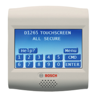
Figure 7: Call for Service Display
The tamper switch activates when someone or
something pulls the D1260/D1260B away from a flat
surface.
3.4 Volume Control
Use a flat-blade screwdriver to adjust the keypad tones’
volume (Item 3 in Figure 4 on page 8).
Figure 8: Increasing and Decreasing Volume

 Loading...