D1260/D1260B | Installation Guide | Contents
.
Bosch Security Systems | 9/04 | 48101E 3
Contents
1.0 Introduction.......................................................4
1.1 Manual Organization .........................................4
1.2 Other Documentation Referenced ...................4
1.3 Documentation Conventions ............................4
1.3.1 Type Styles Used in this Manual ......................4
1.3.2 Tips, Important Notes, Cautions and
Warnings..............................................................4
2.0 D1260/D1260B Overview...............................5
2.1 Parts List ..............................................................6
2.2 Front Panel Features...........................................6
2.2.1 LCD Display .......................................................6
2.2.2 Keypad.................................................................6
2.2.3 Keypad Function Keys.......................................6
2.2.4 Audible Tones.....................................................7
2.3 Internal Features .................................................8
3.0 Installation .........................................................9
3.1 Mounting .............................................................9
3.1.1 Location Recommendations..............................9
3.1.2 Mounting the Back Plate..................................10
3.2 Setting the DIP Switch .....................................10
3.3 Tamper Switch..................................................10
3.4 Volume Control................................................10
3.5 Wiring ................................................................11
4.0 Programming the Control Panel ................12
4.1 Enabling the D1260/D1260B Keypad ...........12
4.2 Programming Area Names..............................13
4.3 Programming Security Company
Information........................................................13
4.3.1 D9412G, D9412 and D9112 Control
Panels .................................................................13
4.3.2 D7412G, D7412, D7212G and D7212
Control Panels...................................................14
4.4 99 + Enter “Setup?” Function .........................14
4.5 Programming Custom Functions ....................14
4.6 Adding “Service Walk” to D7412G/
D7412/D7212G/D7212 Service Menu..........14
5.0 Specifications ..................................................16
Figures
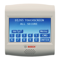
Figure 1: D1260/D1260B Front Panels........................ 5
Figure 2: D1260/D1260B LCD Display....................... 6
Figure 3: D1260/D1260B Keypad ................................ 6
Figure 4: D1260/D1260B with Back Plate
Removed ......................................................... 8
Figure 5: D1260/D1260B Back Plate Mounting
Options ............................................................ 9
Figure 6: D1260/D1260B DIP Switch........................ 10
Figure 7: Call for Service Display............................... 10
Figure 8: Increasing and Decreasing Volume ........... 10
Figure 9: Bosch Control Panel to Keypad Flying
Leads Wiring................................................. 11
Figure 10: Plugging in Wire Connector to
D1260/D1260B............................................. 11
Figure 11: Enhanced Command Center Prompt in
RPS................................................................. 12
Figure 12: Enable Display Revision Prompt in RPS .. 12
Figure 13: High Brightness Settings.............................. 14
Figure 14: Low Brightness Settings............................... 14
Figure 15: Contrast Settings........................................... 14
Tables
Table 1: D1260/D1260B Installation Guide
Organization ................................................... 4
Table 2: Other Referenced Documentation ............... 4
Table 3: Upgrade Kits ................................................... 5
Table 4: Parts List .......................................................... 6
Table 5: D1260/D1260B Dedicated Keys .................. 6
Table 6: Audible Tones................................................. 7
Table 7: D1260/D1260B DIP Switch Settings ......... 10
Table 8: Area/Point Numbers and Area Text.......... 13
Table 9: D1260/D1260B Specifications.................... 16

 Loading...