Bosch | 09/05 | 38685F4
D7039 | Installation Guide |
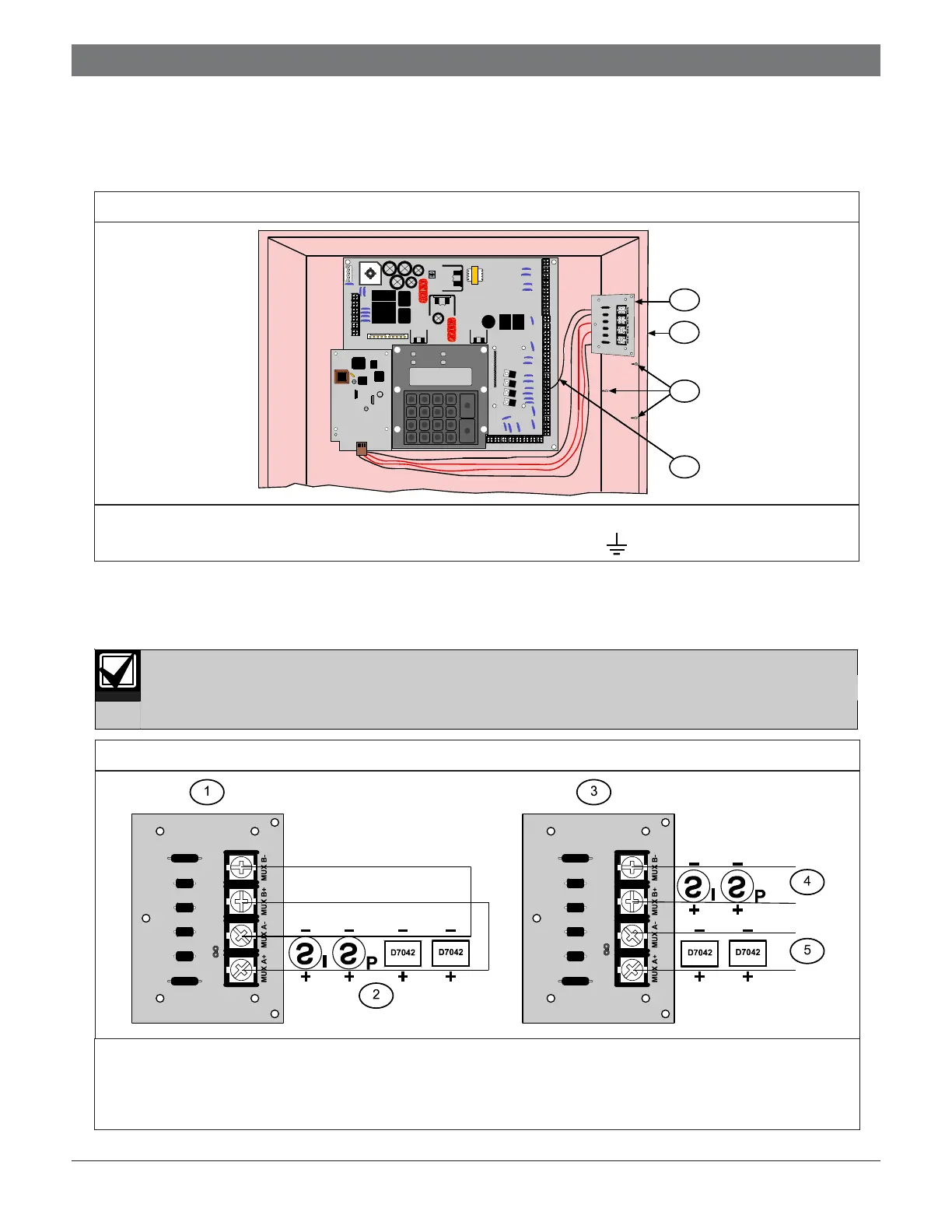
9. Mount the D7039 I/O Module (Item 1 in Figure 3) in the FACP enclosure (Item 2 in Figure 3) using the mounting
holes in the enclosure (Item 3 in Figure 3).
10. Connect the yellow and green earth ground wire from the I/O module to the earth ground terminal on the
FACP control board (Item 4 in Figure 3).
3.0 Wiring
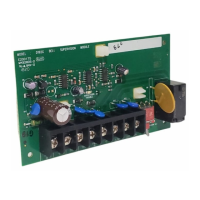
1. Connect the D7039 multiplex loop using up to 3800 ft (1170 m) of 18 AWG (1.0 mm
2
) or 5950 ft (1810 m) of
16 AWG (1.5 mm
2
) wire (Figure 4). Do not use shielded wire.
Do not use shielded wire. Twisted pair is acceptable, but is not recommended.
2.0 Installation
Figure 4: Connecting the Mux Class “A” and Class “B”
1 - I/O module for the D7039, wired Class “A” 4 - Mux B Addresses 129 through 255
2 - Class “A” Addresses 9 through 128 5 - Mux A Addresses 9 through 128
3 - I/O module for the D7039, wired Class “B”
Note: All terminals are supervised.
21 3
4 5 6
7 8 9
#
Cmnd
0
Prog
*
Clear
Disable
Drill
Tes t
History
Reset
Silence
Trouble
Silenced
Power
Alarm
2
1
3
4
1 - I/O module 3 - Holes (3) and standoffs (3) to mount the I/O module
2 - Enclosure 4 - I/O module earth ground wire to the D7024
terminal connection
Figure 3: Installing the Input-Output Module