5Bosch | 09/05 | 38685F
D7039 | Installation Guide | 4.0 Specifications
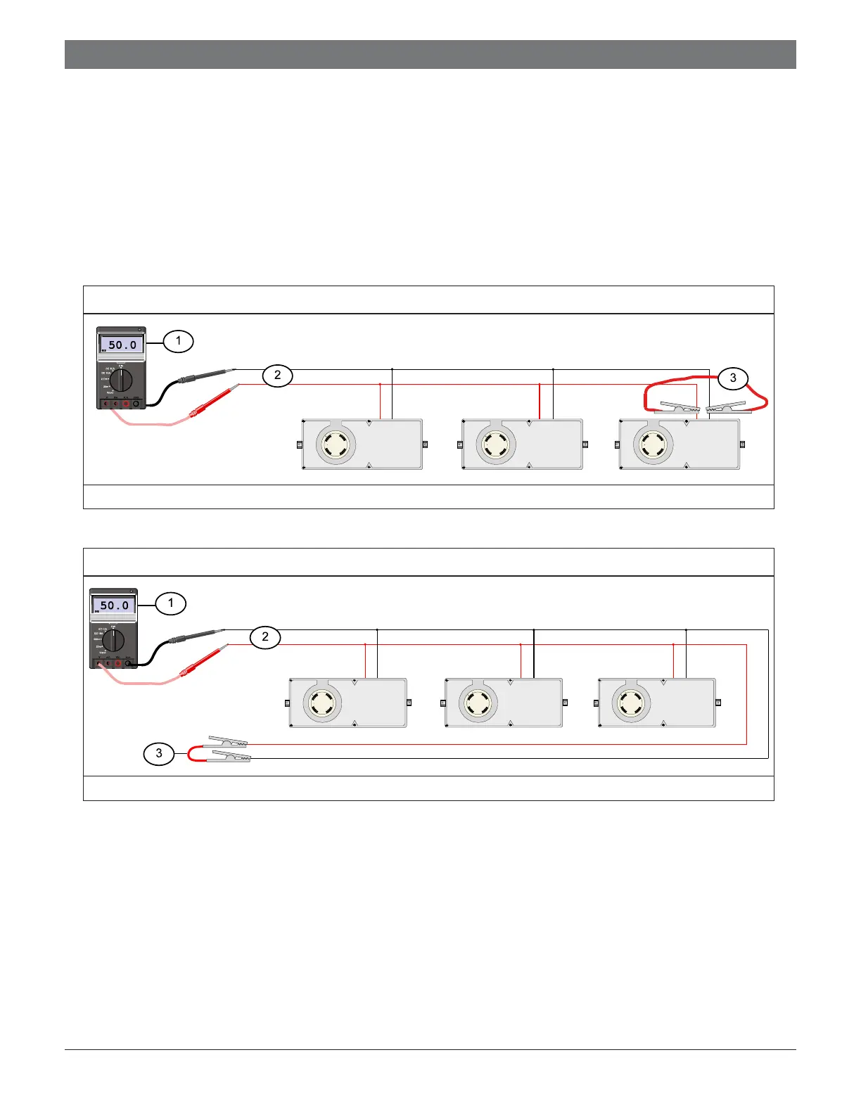
Figure 5: Measuring Class “B” Loop Resistance
1 - 50
Ω
maximum 2 - Mux bus wires 3 - Clip lead
Figure 6: Measuring Class “A” Loop Resistance
1 - 50
Ω
maximum 2 - Mux bus wires 3 - Clip lead
You can configure the D7039 with a single fault tolerant Class “A” loop or as a pair of supervised Class “B”
loops. When configured as a Class “A” loop and installed on a D7024 Control Panel before Lot #100, the
D7039 implements a Style 4.5 signaling line circuit (SLC). When installed on a D7024 Control Panel Lot #100
or later, the D7039 implements Style 6 SLC. Refer to the D7024 Operation and Installation Guide (P/N: 31499)
for programming.
When configured as a Class “B” loop and installed on a D7024 Control Panel before Lot #100, the D7039
implements a Style 3.5 SLC. When installed on a D7024 Control Panel Lot #100 or later, the D7039
implements a Style 4 SLC. Refer to the D7024 Operation and Installation Guide (P/N: 31499) for programming.
2. Measure loop resistance by shorting the end of the farthest device in Class “B” (Figure 5) or shorting the return
wire in Class “A” (Figure 6) and reading the total resistance of all wires associated with the loop.
3. Ensure the loop is disconnected from the D7039 Module.