D7212G Operation and Installation Guide
D7212G
Page 7© 2003 Bosch Security Systems 4998138544C
Contents
Figures
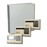
Figure 1: System Configuration ...................................................................................................................................................... 13
Figure 2: Enclosure Mounting ......................................................................................................................................................... 21
Figure 3: Ground Fault Detect ........................................................................................................................................................22
Figure 4: Reset Pin ............................................................................................................................................................................ 22
Figure 5: Non Power Limited Wiring ............................................................................................................................................. 26
Figure 6: Charging and Battery LEDs .......................................................................................................................................... 28
Figure 7: Relays for Terminals 7 and 8 and Ground Start ......................................................................................................30
Figure 8: RJ31X Wiring ..................................................................................................................................................................... 31
Figure 9: Phone Connector and LED and Operation Monitor LED Locations .................................................................. 31
Figure 10: Phone Monitor Select ................................................................................................................................................... 33
Figure 11: On-board Point Sensor Loop Wiring ........................................................................................................................35
Figure 12: Wiring for Installations using the Ademco AB-12 Bell/Housing ........................................................................ 36
Figure 13: Connecting the D8125 POPEX to the D7212G Panel .......................................................................................40
Figure 14: Program Record Sheet ................................................................................................................................................. 41
Figure 15: Connecting D8128D OctoPOPITs to the D7212G .............................................................................................. 45
Figure 16: D8129 Connections to the D7212G ........................................................................................................................48
Figure 17: Power at Command Centers .......................................................................................................................................50
Figure 18: Keyswitch Wiring............................................................................................................................................................ 51
Figure 19: Reset Pin .......................................................................................................................................................................... 57
Figure 20: Programmer and Accessory Connections ............................................................................................................... 58
Figure 21: D7212G Faceplate ........................................................................................................................................................ 59
Figure 22a: D7212G System Wiring Diagram, 1 of 3 ............................................................................................................. 61
Figure 22b: D7212G System Wiring Diagram, 2 of 3 ............................................................................................................. 62
Figure 22c: D7212G System Wiring Diagram, 3 of 3 ............................................................................................................. 63
 Loading...