Easy Series Control Panel Wire the Control Panel | en 7
Bosch Sicherheitssysteme GmbH Quick Installation Guide 2017.01 | 02 | F.01U.306.216
Callout Description
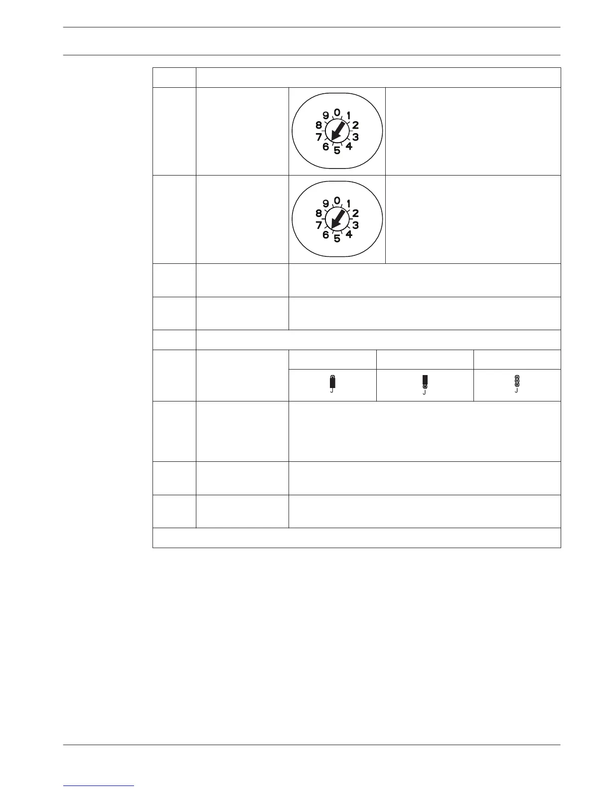
5 B450 Conettix
Plug-in
Communicator
Use address 6.
6 Supervised Points
(single EOL)
Normally open and normally closed options (2.2k Ω)
7 Supervised Points
(dual EOL)
Normally closed (2.2k Ω)
8 Keyswitch Options (single and dual EOL) ((2.2k Ω)
9
Prog Output (PO) 1
Options
Switched 12v Switched Ground Dry Contact
10 Prog Outputs 2 - 4 NF A2P requires that sirens have a backup battery. When this
siren requires a 14,1V to 14,4V supply, use the optional board
EZPS-FRA or the auxiliary power supply IPP-PSU-2A5. Set the
output as interior burglary alarm.
11 2-wire Smoke
Detector Option
EOL resistor (P/N: 25899) required.
12 4-wire Smoke
Detector Option
EOL resistor (P/N: 25899) and Bosch EOL relay module
required
Note: The system uses a 12 VDC battery, connected as shown.
If using RADION devices:
1. Mount the bases for the wireless devices in the desired locations.
Do not attach the wireless devices to the bases at this time.
2. Remove all power from the system.
3. Set the switch on the RADION receiver to normal operating mode = 1.
4. Reapply system power.
Wait for the solid green circle to appear on the control center.
5. Enter the Installer Telephone Menu. Refer to Configuring with the telephone, page 8.
 Loading...