6 en | Wire the Control Panel Easy Series Control Panel
2017.01 | 02 | F.01U.306.216 Quick Installation Guide Bosch Sicherheitssysteme GmbH
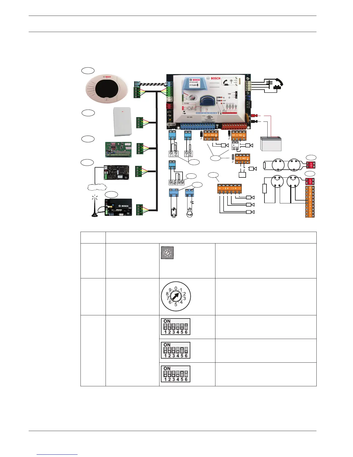
2 Wire the Control Panel
Refer to Figure 2.1 for an overview of the system components and wiring.
IUI-EZ1
1
B
G
Y
R
RFRC-OPT
2
B
G
Y
R
DX2010
3
B
G
Y
R
+
-
9
(+) (-)
10
7
8
B
G
Y
R
B426
6
B
G
Y
R
B450
4
5
11
12
(+) (-)(+) (-)(+) (-)
(+)
(-)
(+)(+)
(+)
(-)
+
(-)
(+)
(-)
Figure 2.1: Wiring diagram
Callout Description
1 Control Center Mount within 3 m of control panel, Use
CAT5 cable (twisted pair) for audio
bus, Set data bus address (1 - 4), up
to 4 controls max
2 RADION receiver 1 = Normal Operation
5 = Maintenance Mode
3 DX2010 Point
Expander
Data bus Adr 102: Points 9-16
Data bus Adr 103: Points 17-24
Data Bus Adr 104: Points 25-32
4 B426 Network
Interface Module
Use address 6.

 Loading...