1:6
Gas Cooktop Operation
Surface Burner Ignition Process
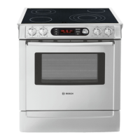
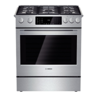
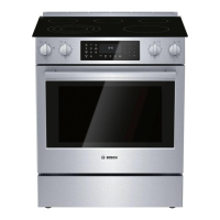
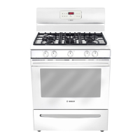
The ignition process of the surface burners on the 300 series and
500 series ranges is identical. Each surface burner is independntly
operated and controlled by a gas valve attached to a common manifold
pipe. The shaft of the valve extends through the front of the manifold
panel located just above the oven door and a knob is installed on the
shaft.
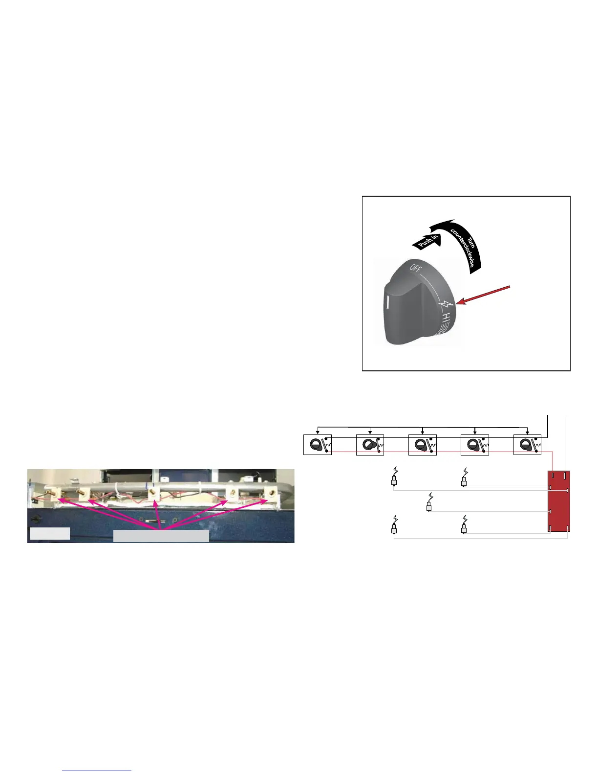
OFF . . . LITE . . HI . . . . . . . . . . . LO
LITE Position Indicator
To operate any surface burner the knob must first be pushed inward
before it can be rotated. When the knob is rotated counterclockwise the
valve opens to allow gas to flow to the burner and activate the electronic
spark module which generates the spark to light the gas.
In order for the burner to light properly the knob must be stopped at the
LITE position indicated on the knob by the lightning bolt graphic shown in
the illustration at right. If the knob is rotated beyond the LITE position no
spark is generatedand the burner will not ignite however gas will continue
to flow to thesurface burner.
Whenever any surface burner control knob is rotated to the LITE
position the spark module will generate a spark at all surface burners
simultaneously even if other burners have already been lighted.
Activation of the spark module is accomplished by means of a switch
that fits onto each surface burner control valve as seen in photo A below.
As the valve is rotated the switch cam is rotated.
The surface igniter switches are assembled in a continuous harness
and wired in a parallel circuit allowing any one of them to activate the
spark module. If one switch is defective they must all be replaced as an
assembly.
In the illustration above the eft Rear surface igniter switch is rotated
to the LITE position closing the contact in the switch and supplying L1
voltage to the spark module. The module fires all surface burner igniters
at the same time.
IGNITER SWITCHES
Photo A