English | 33
Bosch Power Tools 1 609 92A 3XP | (30.6.17)
55 Screws for insert plate
56 Material stop*
57 Lock screw of the material stop*
58 Clamping screw of the material stop*
59 Adjustment screw for laser positioning (right of the saw
blade)
60 Hex key (2,5 mm)
61 Adjustment screw for laser positioning (left of the saw
blade)
62 Screws for laser protection cap
63 Fastening screw for laser mounting plate
64 Fastening screw for laser housing
65 Stop screw for 0° bevel angle
66 Stop screw for left-hand bevel angle range
67 Stop screw for right-hand bevel angle range
68 Set screws of scale 26 for mitre angles
69 Screw for mitre angle indicator
70 Velcro strap
*Accessories shown or described are not part of the standard de-
livery scope of the product. A complete overview of accessories
can be found in our accessories program.
Noise Information
Sound emission values determined according to
EN 62841-3-9.
Typically the A-weighted noise levels of the product are:
Sound pressure level 95 dB(A); Sound power level
106 dB(A). Uncertainty K =3 dB.
Wear hearing protection!
The noise emission value given in these instructions has been
measured in accordance with a standardised measuring pro-
cedure and may be used to compare power tools. It may also
be used for a preliminary estimation of noise emissions.
The noise emission value given represents the main applica-
tions of the power tool. However, if the power tool is used for
other applications, with different accessories or is poorly
maintained, the noise emission value may differ. This may sig-
nificantly increase noise emissions over the total working pe-
riod.
To estimate noise emissions accurately, the times when the
tool is switched off, or when it is running but not actually being
used, should also be taken into account. This may significant-
ly reduce noise emissions over the total working period.
Technical Data
Assembly
Avoid unintentional starting of the machine. During as-
sembly and for all work on the machine, the power plug
must not be connected to the mains supply.
Delivery Scope
Before starting the operation of the machine for the first time,
check if all parts listed below have been supplied:
– Sliding mitre saw with mounted saw blade
– Quick-action clamp 38
–Hex key 37
–Hex key 60
–SDS bolt30
Note: Check the power tool for possible damage.
Before further use of the machine, check that all protective
devices are fully functional. Any lightly damaged parts must
be carefully checked to ensure flawless operation of the tool.
All parts must be properly mounted and all conditions fulfilled
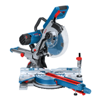
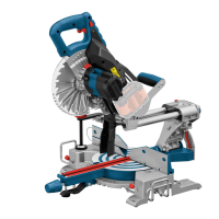
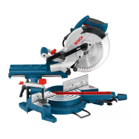
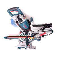
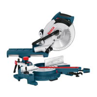
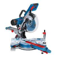
Sliding Mitre Saw GCM 350-254
Article number 3 601 M22 ...
... 6.. ... 640 ... 660 ... 6B0
Rated power input
W 1800 1800 1450 1800
No-load speed
min
-1
3700–5000 3700–5000 4600 3700–4600
Reduced starting current
–
Laser type
nm
mW
650
<0.39
650
<0.39
650
<0.39
650
<0.39
Laser class
1 111
Divergence of laser line
1.0 mrad (full angle) 1.0 mrad (full angle) 1.0 mrad (full angle) 1.0 mrad (full angle)
Weight according to EPTA-
Procedure 01:2014
kg 24.2 24.2 24.2 24.2
Protection class
/II /II /II /II
Dimension of suitable saw blades
Saw blade diameter
mm 254 254 254 254
Blade body thickness
mm 1.7–2.6 1.7–2.6 1.7–2.6 1.7–2.6
Max. cutting width
mm 3.2 3.2 3.2 3.2
Mounting hole diameter
mm 30 25.4 30 25.4
Permissible workpiece dimensions (maximum/minimum) see page 37.
The values given are valid for a nominal voltage [U] of 230 V. For different voltages and models for specific countries, these values can vary.
OBJ_BUCH-2953-002.book Page 33 Friday, June 30, 2017 11:46 AM
 Loading...