English | 43
Bosch Power Tools 1 609 929 X56 | (22.1.11)
External Dust Extraction (see figure G)
To connect a vacuum cleaner to the sawdust
ejector 31, use the supplied extraction adapter
32.
– Firmly attach the extraction adapter 32 and
the vacuum hose.
– Additionally, a dust extraction system can be
connected to vacuum connection 7 to in-
crease the extraction performance.
The vacuum cleaner must be suitable for the ma-
terial being worked.
When vacuuming dry dust that is especially det-
rimental to health or carcinogenic, use a special
vacuum cleaner.
Stationary or Flexible Mounting
f To ensure safe handling, the machine must
be mounted on a level and stable surface
(e. g., workbench) prior to using.
Mounting to a Working Surface (see figure H)
– Fasten the power tool with suitable screw
fasteners to the working surface. The mount-
ing holes 12 serve for this purpose.
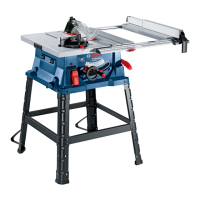
Mounting to a Bosch Saw Stand (see figure I)
With the height-adjustable legs, Bosch saw
stands (e. g. GTA 60 W, GTA 600) provide firm
support for the power tool on any surface.
f Read all safety warnings and instructions
included with the worktable. Failure of ob-
serving safety warnings and instructions can
lead to electrical shock, fire and/or cause se-
rious injuries.
f Assemble the worktable properly before
mounting the power tool. Perfect assembly
is important in order to prevent the risk of
collapsing.
– Mount the power tool on the saw stand in the
transport position.
Changing the Saw Blade
(see figures J1– J4)
f Before any work on the machine itself, pull
the mains plug.
f When mounting the saw blade, wear protec-
tive gloves. Danger of injury when touching
the saw blade.
Use only saw blades whose maximum permitted
speed is higher than the no-load speed of the
power tool.
Use only saw blades that correspond with the
characteristic data given in these operation in-
structions and that are tested and marked in ac-
cordance with EN 847-1.
Use only saw blades recommended by the tool
manufacturer, and suitable for sawing the mate-
rials to be cut.
Removing the Saw Blade
– Using a screwdriver, raise the insert plate 24
at the front and remove it from the tool ba-
sin.
–Turn crank 19 clockwise to the stop, so that
the saw blade 26 is in the highest possible
position above the saw table.
– Tilt the protection guard 6 toward the rear to
the stop.
– Turn the clamping nut 42 with the ring span-
ner 22 (23 mm) and at the same time, pull
the spindle lock lever 43 until it engages.
– Keep the spindle lock lever pulled and un-
screw the clamping nut turning in anticlock-
wise direction.
– Remove the clamping flange 44.
– Remove the saw blade 26.
Mounting the Saw Blade
If required, clean all parts to be mounted prior
to assembly.
– Place the new saw blade onto the supporting
flange 46 of the tool spindle 45.
Note: Do not use saw blades that are too small.
The clearance between saw blade and riving
knife must not exceed 5 mm (max.).
OBJ_BUCH-1325-001.book Page 43 Saturday, January 22, 2011 12:54 PM

 Loading...
