6 720 808 907 (2014/04) MM100
86 | Product details
2.4 Cleaning and care
▶ If required, wipe the enclosure with a damp cloth. Never
use chemically aggressive or acidic cleaning agents.
2.5 Supplementary accessories
For precise information regarding suitable accessories, refer to
the catalogue.
• For heating circuits with or without mixing valve actuators
and constant heating circuits:
– Heating pump; connection to PC1
– Flow temperature sensor for low loss header (optional;
not possible with all user interfaces); connection to T0
– Temperature switch; connection to MC1; when limit
temperature is exceeded, power supply to terminal 63
- PC1 is interrupted; if there is no temperature switch in
the heating circuit without mixer or in the constant
heating circuit, connect jumper ( Fig. 1 [2],
page 100) to MC1 included in standard delivery.
• Additional accessories for heating circuit with mixer:
– Mixing valve actuator; connection to VC1
– Flow temperature sensor in assigned heating circuit;
connection to TC1
• Additionally, for a heating circuit in conjunction with a heat
pump (heating/cooling):
– Dew point monitor; connection to MD1; sends a signal
to the control when the dew point is reached, in order
to avoid condensate formation by further cooling, and
stops the heating pump
• Additionally, for a constant heating circuit:
– External signal for heat requirement; connection to
MD1 (the pump is only switched on if the external heat
requirement is enabled on the user interface)
– Mixing valve actuator (optional); connection to VC1
– Flow temperature sensor in assigned heating circuit
(optional); connection to TC1
• For cylinder primary circuit (e.g. after low loss header):
– Cylinder primary pump; connection to PC1; connect
jumper ( Fig. 1 [2], page 100) to MC1
– DHW circulation pump (optional); connection to VC1
(terminal 43: DHW circulation pump phase/terminal
44: not assigned)
– Flow temperature sensor for low loss header (optional;
not possible with all user interfaces); connection to T0
– Cylinder temperature sensor; connection to TC1.
Installation of additional accessories
▶ Install additional accessories according to legal
requirements and the instructions supplied.
Unless otherwise stipulated in the instructions supplied with
the dew point monitor or heat pump:
▶ Install condensation point sensor as near as possible on the
buffer cylinder or on the coolest point of the system.
▶ Connect max. 4 dew point monitors in parallel to MD1.
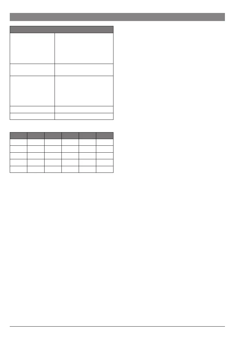
Temperature sensor
capturing range
• lower fault limit
• display range
• upper fault limit
• <-10 °C
• 0 ... 100 °C
• > 125 °C
Permissible ambient
temperature
0 ... 60 °C
IP rating
• For installation in
heat source
• For wall-mounted
installation
• Determined by the IP rating of
the heat source
• IP 44
Protection class I
ID no. Data plate ( Fig. 15, page 105)
°C °C °C
8 25065 38 7174 68 2488
14 19170 44 5730 74 2053
20 14772 50 4608 80 1704
26 11500 56 3723 86 1421
32 9043 62 3032 – –
Table 4 Test values for the flow temperature sensor
(included in standard delivery)
Technical data
Table 3



 To Next Page
 Loading...