Installation
MS 200 – 6720879925 (2017/11)
28
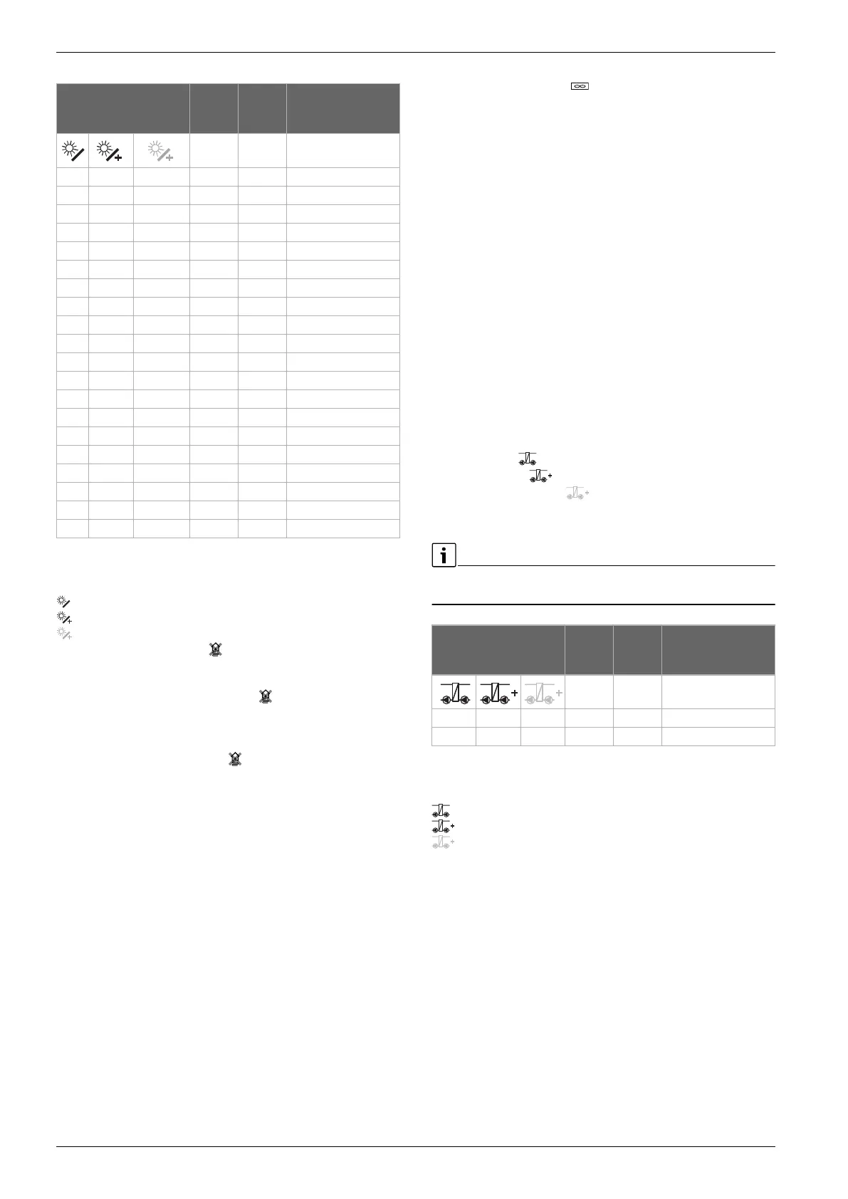
Table 7 Examples often with realized solar systems
(note limitations in combination with the interface of a heating
pump (HPC 400/HPC 410/HMC300/HMC310))
Solar thermal system
Solar function
Additional function (shown in grey)
A Central heating backup ( )
B 2rd cylinder with valve
C 2nd cylinder with pump
D Central heating backup 2 cylinder ( )
E External heat exchanger at cylinder 1
F External heat exchanger at cylinder 2
G 2nd collector array
H Return temperature control ( )
I Transfer system
J Transfer system with heat exchanger
K Thermal disinfection
L Heat meter
M Temp. differential controller
N 3rd cylinder with valve
P Pool
Q External heat exchanger at cylinder 3
Collector cooling function
The collector cooling function is a Delta regulation. Temperatures that
are too high should be avoided by cooling the collector. The heat build-up
in a collector is transferred to the emergency cooling device via a pump.
The hydraulic circuit is comparable to function C. It is not possible to cool
two collector arrays.
In the case of an error of the collector temperature sensors, the collector
cooling function is not operational.
The function is only released in the menu when the corresponding
terminals are free.
Connection options for pump (PS10) for the cooling function:
▶ If only MS 200 is present, on the MS 200 on terminals, connect PS4
( Fig. 38 at the and of the document).
-or-
▶ If MS 200 and MS 100 are present, connect to the MS 100 on the
terminals PS3 (without Fig).
Transfer and primary store systems
You will find the required connections and the corresponding hydraulics
diagrams for these examples, in the appendix.
The designation of the connection diagram to the transfer and primary
store systems can be made easier by answering the following questions:
• Which system is present?
• Which functions (shown in black) are available?
• Are additional functions available? The additional functions
(shown in grey) can enable the prior selected transfer/primary store
systems, to be expanded.
A description of the transfer and primary store systems can be found in
a chapter more towards the beginning of this document.
Table 8 Examples often with realized solar systems
(note limitations in combination with the interface of a heating
pump (HPC 400/HPC 410/HMC300/HMC310))
Transfer or primary store system
Transfer or primary store function
Additional function (shown in grey)
A Thermal disinfection
3.2.4 Overview of the terminal assignment
This overview indicates examples of which system parts can be
connected for all terminals in the module. The components identified
with * (such as VS1 and VS3) in the system, are possible alternatives.
Depending on the module's use, one of the components is connected to
the “VS1/PS2/PS3” terminal.
More complex solar systems can be realised in combination with a
second solar module. Terminal assignments, which deviate from the
terminal overview, are possible with this option ( Wiring diagrams
with system examples).
Solar system MS 200 MS 100 Wiring diagram at
the end of the
document
1 A – – 1A
1 A GHK – 1A (GHK)
1AE GH – 1AE (GH)
1 B AGHKP – 1B (AGHKP)
1 BD GHK – 1BD (GHK)
1 BDF GH – 1BDF (GH)
1 C DHK – 1C (DHK)
1 ACE HP – 1ACE (HP)
1 BDI GHK – 1BDI (GHK)
1 BDFI GHK 1BDFI (GHK)
1 AJ BKP – 1AJ (BKP)
1 AEJ BP – 1AEJ (BP)
1 ABEJ GKMP 1ABEJ (GKMP)
1 ACEJ KMP 1ACEJ (KMP)
1 BDNP HK – 1BDNP (HK)
1 BNFNP H – 1BDFNP (H)
1 BNFNP GHKM 1BDFNP (GHKM)
1 BNQ – – 1BNQ
1 ... ... K – 1... (K)
1 ... ... L – 1... (L)
System MS 200 MS 100 Wiring diagram at
the end of the
document
3 A – – 3A
4 – – – 4
 Loading...