EasyManuals Logo

Bosch PLN-24CH10 User Manual

Bosch PLN-24CH10
24 pages
To Next Page IconTo Next Page
To Previous Page IconTo Previous Page
Page #13 background imageLoading...
Page #13 background image
Bosch Security Systems | 2006-11 | 9922 141 50781 en
Plena 24 VDC Battery Charger | Installation and User Instructions | Equipment en | 13
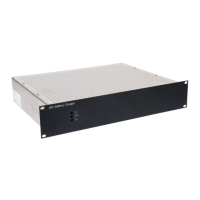
3.3 External connections
3.3.1 Battery
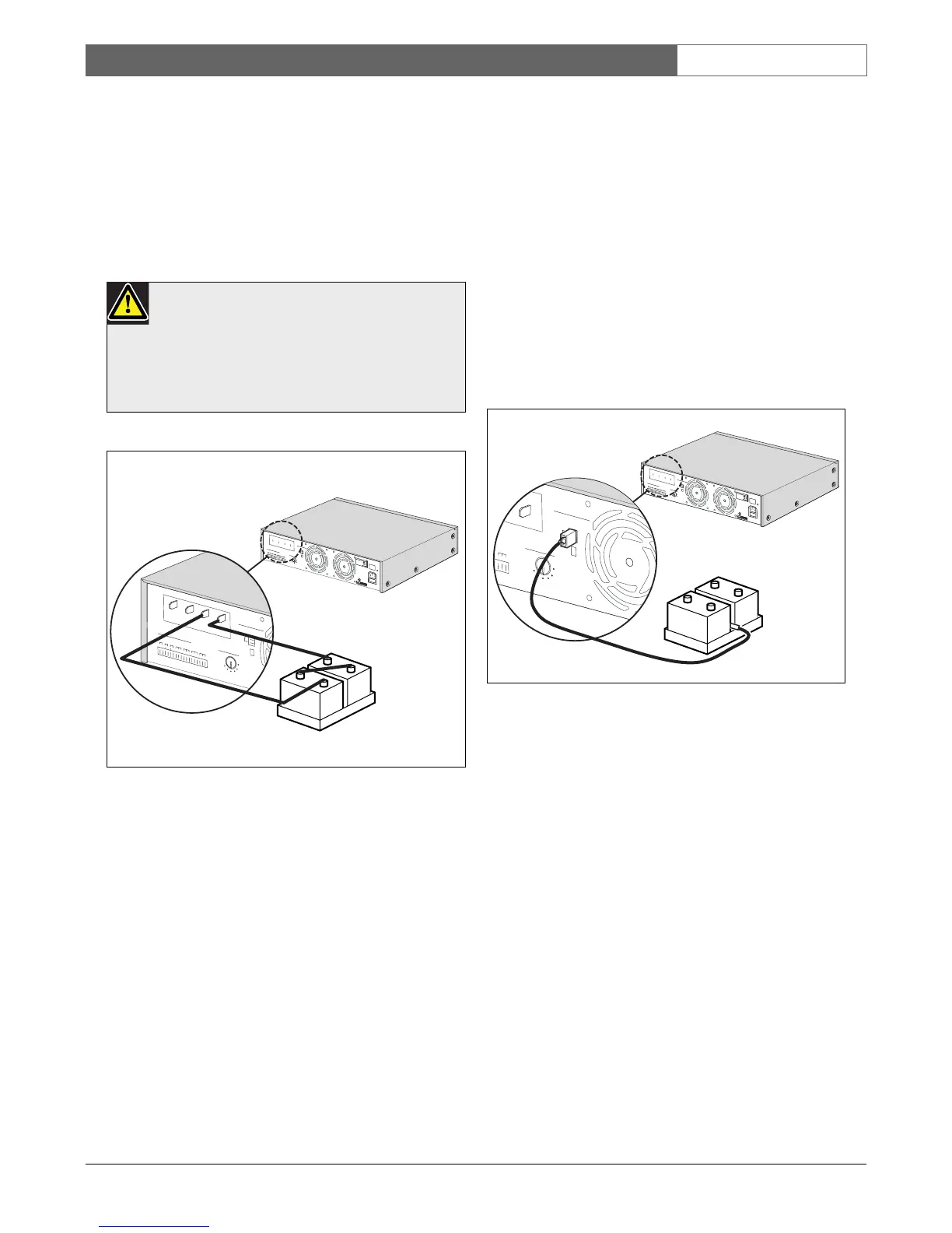
The battery charger has 2 screw terminal connections to
the battery. Connect In + to the plus terminal of the
battery, connect the In - to the minus terminal of the
battery (see example in figure 3.5).
3.3.2 Back-up power connection
The battery charger has 2 screw terminal for connecting
to the Voice Alarm System or public address system.
Connect Out + to the plus terminals of the system
components, connect the Out - to the minus terminal of
the system components.
It is recommended that this back-up power connector is
not used for the Remote Control Panels or volume
overrides. Use the 24V DC output connectors.
Refer to 3.3.4.
3.3.3 Temperature sensor
The battery charger has one connector for a
temperature sensor, which is supplied with the battery
charger.
To improve the lifetime of the battery, applied voltages
and current are temperature dependant; therefore,
connect the sensor in such a way that a good thermal
reading is possible. For example, you can either connect
the sensor to the battery tray, or place it between two
batteries (see figure 3.6). If the temperature sensor is not
being used, the slide switch for the temperature sensor
should be set to off.
Caution
Always connect the batteries in series as shown
in figure 3.5. The total sum of the batteries must
equal 48 Volts. Only use batteries of equal
voltage, capacity and type.
figure 3.5: Connecting batteries to charger (example)
O
F
F
50-
20
0A
h
25-
50
A
h
13-
25
A
h
7-
13A
h
4-
7A
h
2-
4
A
h
O
N
+
+
-
+
I
n
-
Ma
i
ns
Batter
y
C
a
pa
c
i
ty
T
emp
er
a
ture
s
e
n
sor
RCP
1
+-
-
-
2
4
V
DC
outp
ut/
Tr
i
g
g
er
O
ut
-O
ut
+
+
-
RCP1
F
a
u
l
t
B
a
t
t
e
ry
2
4VDC
O
u
t
B
at
t
e
r
y
i
n
U
s
e
-
+
-
+
12 VDC
12 VDC
D
e
s
i
gn
&
Q
u
a
li
t
y
T
h
e
N
e
th
e
r
l
a
n
d
s
P
L
N
-
2
4
C
H
1
0
N
L
-
4
8
2
7
HG-
1
0
P
l
e
n
a
D
C
P
o
w
e
r
Su
p
pl
y
A
n
d
Ba
t
t
e
r
yC
h
a
r
g
e
r
-
2
4
9
0
0
V
~
,
50
/
6
0
H
z
S
/
N
.
8
9
0
1
9
6
5
0
0
0
0
1
A
0
35
4
1
3
M
a
d
e
i
n
C
h
i
n
a
N
6
6
3
P
ow
e
r
R
a
t
e
d
i
n
pu
t
P
ow
e
r
:
55
0V
A
A
ppa
ra
t
u
s
d
e
l
i
v
e
r
e
d
c
on
n
e
c
t
e
d
f
or
1
00-
240V
~
,50
/60H
z
L
i
n
e
f
u
s
e
:
T
1
0L
2
50V
O
F
F
50-200A
h
25-50A
h
13-25
A
h
7-13A
h
4-7A
h
2-4A
h
O
N
+
+
-
+I
n
-
M
a
i
n
s
B
at
t
e
ry
Cap
ac
i
ty
Temp
e
rat
ure
s
e
n
sor
R
C
P
1
+
-
-
-
2
4
V
D
C
ou
t
put
/
Tri
g
ge
rOu
t
-
Ou
t+
+
-
R
C
P
1
Fa
u
l
t
B
a
t
t
e
r
y
24V
D
C
Ou
t
B
a
t
t
e
r
y
i
n
U
s
e
figure 3.6: Connecting the temperature sensor
-
D
e
s
i
gn
&
Q
u
a
li
ty
T
h
e
N
e
th
erla
n
d
s
P
L
N
-
2
4
C
H
1
0
N
L
-
4
8
2
7
HG
-
1
0
Pl
e
n
a
D
C
Po
w
e
r
S
u
p
pl
y
A
n
d
B
a
t
t
e
r
yC
h
a
r
g
e
r
-
2
4
9
0
0
V
~
,
5
0
/
6
0
H
z
S
/
N
.
8
9
0
1
9
6
5
0
0
00
1
A
0
35
4
1
3
M
a
d
ei
n
C
h
i
n
a
N
6
6
3
P
o
wer
R
a
t
e
d
i
n
pu
t
P
ower
:
55
0V
A
A
pp
a
r
a
t
u
s
d
e
l
i
v
e
r
e
d
c
on
n
e
c
t
e
d
f
or
1
00-
240V
~
,50
/
60Hz
L
i
n
e
f
u
s
e
:
T
1
0
L
2
50
V
O
F
F
5
0-2
00A
h
25
-50A
h
13
-
2
5A
h
7
-13A
h
4-
7A
h
2
-
4A
h
O
N
+
+
-
+I
n
-
M
a
i
n
s
B
at
t
ery
Cap
ac
i
ty
Tem
p
e
rat
ure
s
e
n
sor
R
C
P
1
+
-
-
-
2
4
V
D
C
ou
t
put
/
T
ri
g
ge
rOu
t
-
Out +
+
-
R
C
P
1
F
a
u
l
t
B
a
t
t
e
r
y
2
4VDC
Ou
t
B
a
t
t
e
r
y
i
n
U
s
e
OF
F
5
0
-
2
0
0
A
h
2
5
-
5
0
A
h
1
3
-
2
5
A
h
7
-
1
3
A
h
4
-
7
A
h
2
-
4
A
h
ON
+
+
-
+In-
M
a
i
ns
BatteryC
a
pa
city
Temperature sensor
y
-
+
-
+
12 VDC
12 VDC

Questions and Answers:

Question and Answer IconNeed help?

Do you have a question about the Bosch PLN-24CH10 and is the answer not in the manual?

Bosch PLN-24CH10 Specifications

General IconGeneral
BrandBosch
ModelPLN-24CH10
CategoryBattery Charger
LanguageEnglish

Related product manuals