Bosch Security Systems | 2006-11 | 9922 141 50781 en
Plena 24 VDC Battery Charger | Installation and User Instructions | Operation en | 17
4Operation
4.1 Power on and off
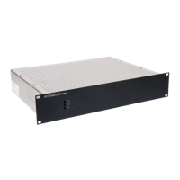
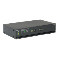
4.1.1 Switch on
Put the Power switch on the rear of the Battery Charger
(see figure 4.1) in the I position.
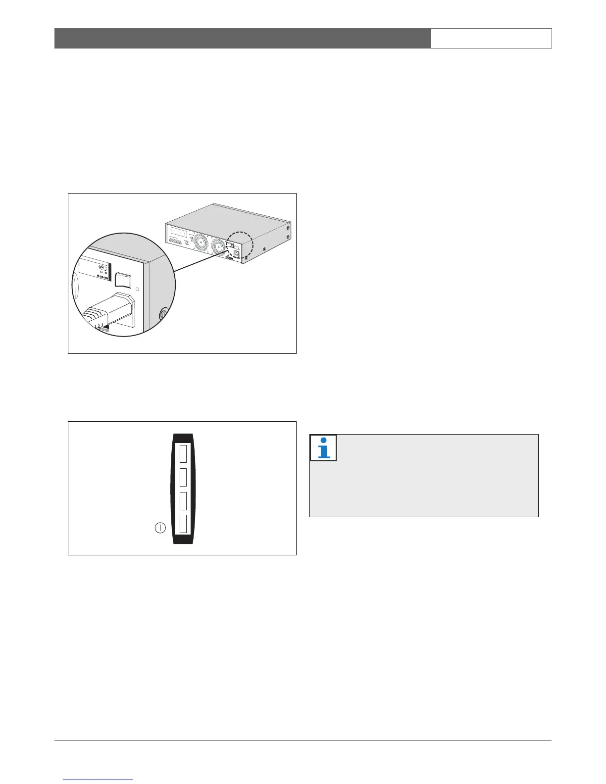
When mains power is available, the power indicator on
the front of the battery charger is lit (see figure 4.2).
4.2 Switch off
Put the Power switch of the battery changer (see figure
4.1) in the O position.
4.3 Battery capacity
4.3.1 Introduction
A rotary Battery Capacity switch at the rear of the unit is
used to adjust the output current to the capacity of the
battery. To comply with the IEC 60849 standard, the
first 80% charge capacity of the battery has to be
charged within the first 24hours. The full charge is
complete in the following 24 hours.
4.3.2 Charging modes
The battery charger has 4 charging modes:
• Bulk mode - Charging state always start with Bulk
mode. A constant current source is used for the
battery charging in this state.
• Full mode - When the battery voltage greater than
the threshold, the battery charger goes to full mode.
A constant voltage is used to complete the charge of
the battery. Once the charging current drops below a
certain threshold, battery is defined as full charged
and charger goes to the float-mode.
• Float mode - A constant trickle charge lower than
Full mode, that maintains battery capacity.
• Equalization - Once a month the charger charges the
battery with the 3 modes to keep the battery in good
condition.
figure 4.1: Power switch
figure 4.2: Power indicator
D
e
s
i
gn
&
Q
u
a
li
t
y
T
h
e
N
e
th
e
r
l
a
n
d
s
P
L
N
-
2
4
C
H
1
0
N
L
-
4
8
2
7
H
G
-
1
0
P
l
e
n
a
D
C
P
o
w
e
r
Su
p
p
l
y
A
n
d
Ba
t
t
e
r
y
C
h
a
r
g
e
r
-
2
4
9
0
0
V
~
,
50
/
6
0
H
z
S
/
N
.
8
9
0
1
9
6
5
0
0
0
0
1
A0
35
4
1
3
M
a
d
e
i
n
C
h
i
n
a
N
6
63
P
ow
e
r
R
a
t
e
d
i
n
pu
t
P
ower
:
55
0V
A
A
ppa
r
a
t
u
s
d
e
l
i
v
e
r
e
d
c
on
n
e
c
t
e
d
f
o
r
90-
2
40V
~
,
5
0
/
60Hz
L
in
e
f
u
s
e
:
T
1
0L
2
5
0V
O
F
F
50
-
2
00
A
h
2
5
-5
0
A
h
1
3
-25A
h
7-
13A
h
4
-
7A
h
2-4
A
h
O
N
+
+
-
-I
n+
Ma
i
n
s
B
at
t
e
ry
C
ap
ac
i
ty
Tem
p
e
rat
u
re
s
e
n
sor
R
CP
1
+
-
-
-
2
4
V
DC
ou
t
put
/
Tri
g
ge
rOu
t
-
Out +
+
-
R
C
P
1
F
a
u
l
t
B
a
t
t
e
r
y
2
4
V
D
C
O
ut
B
a
t
t
e
r
y
i
n
U
s
e
 Loading...