Installation 39/68
RE 92105-01-B/06.2017, A4CSG, Series 3x, Bosch Rexroth AG
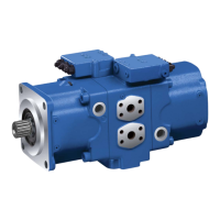
Fig. 12: Port overviewA4CSG, EP control
Table 10: Ports A4CSG series 1x and 3x
Ports
1)
p
max
[bar]
2)
State
3)
A, B Working port (high-pressure series)
Fastening thread
400 O
S Suction port fastening thread 30 O
M
S
Suction pressure measurement 30 X
K
1
Flushing port 5 O
K
2
, K
3
Flushing port 4 X
4)
M
A
, M
B
, M
ABP
Working pressure measurement 400 X
M
1
, M
2
Control pressure measurement 400 X
E
1
Filter, supply 40 X
E
2
Filter, return 40 X
E
3
Boost port (external) 40 X
M
E3
Boost pressure measurement 40 X
K
4
Accumulator (external) 40 X
M
K4
Flushing pressure measurement 40 X
R(L) Fluid filling + air bleeding 4 O
4)
T Fluid drain 4 X
4)
T
1
DB valve relief port X
4)
U Flushing port (bearing flushing) 7 X
X
A2
, X
B2
, X
AB
Pilot pressure port for pressure
controller
400 O
1)
The measuring system and thread size can be taken from the installation drawing.
2)
Short-term pressure spikes may occur depending on the application. Keep this in mind when
selecting measuring devices and fittings.
3)
O = Must be connected (plugged when delivered)
X = Plugged (in normal operation)
4)
Depending on the installation position, K
1
, K
2
or K
3
must be connected
Port overview
K
2
B
R(L)
M
2
M
B
M
ABP
E
1
E
2
E
3
M
E3
U
K
3
A TSK
1
K
4
M
K4
M
A
M
S
M
1
T
1
X
A2
X
AB
X
B2
 Loading...