EasyManua.ls Logo

Bosch Rexroth A7VO 63 Series User Manual

Bosch Rexroth A7VO 63 Series
42 pages
To Next Page IconTo Next Page
Page #1 background imageLoading...
Page #1 background image
RE 92202/02.2015, Bosch Rexroth AG
Characteristics
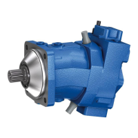
Variable pump with axial tapered piston rotary group of
bent-axis design, for hydrostatic drives in open circuit
For use in mobile and stationary applications
Flow is proportional to the drive speed and displace-
ment.
The flow can be steplessly changed by adjusting the
bent axis.
Wide selection of control devices
Compact, robust pump with a long service life
Sizes 28 to 160
Nominal pressure 350bar
Maximum pressure 400bar
Open circuit
Axial piston variable pump
A7VO Series 63
RE 92202
Edition: 02.2015
Replaces: 05.2012
Ordering code 2
Hydraulic fluids 4
Shaft seal ring 5
Flow direction 5
Operating pressure range 6
Technical data 7
LR – Power controller without power override 9
LA1 – Power controller with hydraulically
proportional power override 13
DR – Pressure controller 15
HD – Proportional hydraulic control 18
EP – Proportional electric control 20
Dimensions, size 28 21
Dimensions, size 55 24
Dimensions, size 80 28
Dimensions, size 107 32
Dimensions, size 160 36
Connector for solenoids 40
Installation instructions 41
Project planning notes 42
Safety instructions 42
Contents
Question and Answer IconNeed help?

Do you have a question about the Bosch Rexroth A7VO 63 Series and is the answer not in the manual?

Bosch Rexroth A7VO 63 Series Specifications

General IconGeneral
BrandBosch
ModelRexroth A7VO 63 Series
CategoryWater Pump
LanguageEnglish

Summary

Ordering Code

LR - Power Controller without Power Override

Characteristic Curve LR

Graphical representation of the power controller's operating characteristic.

Schematic LR

Hydraulic schematic diagram for the LR power controller.

LRD - Power Controller with Pressure Cut-off

Characteristic Curve LRD

Shows the pressure cut-off characteristic for the LRD controller.

Schematic LRD

Hydraulic schematic diagram for the LRD power controller.

LR... - Power Controller with Stroke Limiter

LRH1 – Hydraulic Stroke Limiter (Negative Control)

Details the LRH1 control for limiting pump displacement.

LRDS - Power Control with Pressure Cut-off and Load Sensing

Characteristic Curve LRDS

Operating pressure characteristic for the LRDS controller.

Schematic LRDS

Hydraulic schematic diagram for the LRDS controller.

LA1 - Hydraulic Proportional Power Override

LA1S - Power Controller with Load Sensing

Details the LA1S variant for load sensing applications.

LA1S5 - Hydraulic Proportional LS-Override

Characteristic Curve LA1S5

Shows differential pressure vs. pilot pressure for LA1S5.

Schematic LA1S5

Hydraulic schematic diagram for the LA1S5 controller.

DR - Pressure Controller

Schematic DR

Hydraulic schematic for the DR pressure controller.

Characteristic Curve DR

Graph of operating pressure vs. flow for the DR controller.

DRG - Remotely Controlled Pressure Controller

Characteristic Curve DRG

Operating pressure vs. flow characteristic for DRG.

Schematic DRG

Hydraulic schematic for the DRG controller.

DRS - Pressure Controller with Load Sensing

Characteristic Curve DRS

Operating pressure vs. flow characteristic for DRS.

Schematic DRS

Hydraulic schematic diagram for the DRS controller.

HD - Proportional Hydraulic Control

Characteristic Curve HD1 Positive Control

Graph of pilot pressure vs. displacement for HD1.

Schematic HD

Hydraulic schematic diagram for the HD controller.

HD1G - Proportional Hydraulic Control with Pressure Cut-off

EP - Proportional Electric Control

Safety Instructions

Related product manuals