18/24 4THE5 | Installation
Bosch Rexroth AG, RE29696-01-B/2021-06-15
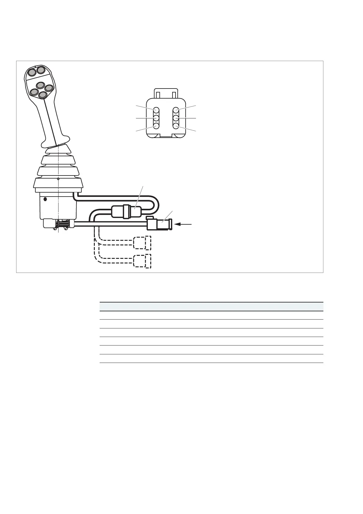
7�3�5 Electrically connecting the joystick
Pin 1
Pin 3
Pin 2
Pin 6
Pin 4
Pin 5
Y
1
2
3
4
Connector
DEUTSCH DT04–06P–CE03
View Y
1 Control grip connector 12S
2 Supply and CAN connector 6P
3 Optional connector for
analogical options 8S
– Supply 5V for auxiliary functions
– Voltage input from potentiometer or
push button
4 Optional connector for
on/off options 8P
– Inputs outputs at V bat.
Fig. 4: Pin assignment
Table 6: Pin assignment
Pin CAN version PWM version Analog version
1 V
Bat
5 V regulated 5 V regulated
2 GND GND GND
3 CAN_IN High Axis 1 Principal Axis 1 Principal
4 CAN_IN Low Axis 1 Redundant Axis 1 Redundant
5 CAN_OUT High Axis 2 Principal Axis 2 Principal
6 CAN_OUT Low Axis 2 Redundant Axis 2 Redundant
1� Make sure that the DEUTSCH mating connector is in de-energized condition.
2� Connect the mating connector of the wiring harness to the joystick connector
until it engages noticeably and observe the correct plug-in position.
3� The joystick is ready for operation within
– 1500ms (CAN version)
– 5ms (Analog and PWM version)
after the voltage supply is applied.