3 608 870 0D6/2011-12 |
LTS350D/LTE350D Bosch Rexroth AG 23
/88
ENGLISH
ENGLISH
ITALIANO
ESPAÑOL
PORTUGUÊS
SVENSKA
FRANÇAIS
Language packs
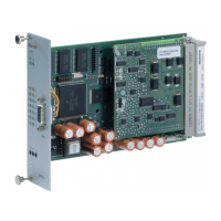
The language pack for the LTS350D/
LTE350D servo amplifiers is uploaded to the
controller using the BS350 operating pro-
gram. This is done via the menu item “Config-
uration | HMI SE/CS” in the BS350.
LED display and reset button
There are three LEDs on the front panel of the
servo amplifier to indicate the operating state.
XDS1 interface for ErgoSpin hand-
held nutrunner
The ErgoSpin hand-held nutrunner is
connected to the servo amplifier via a spindle
connection cable that is connected to the
11-pin connection socket. The power supply
for the motor, logic supply, and transmission
of interface signals is provided via this cable.
Fig. 3: Socket, view from front side
Tab. 5
LED/
button
Display Diagnosis
BTB
Off
No power supply or LTS/LTE
is in download mode
Green Ready for operation
Green,
flashing
Not ready for operation, but
no system error; Motor stop
has been triggered
FG
Off No servo amplifier release
Green Servo amplifier release
Error
Red System error
Reset
When pressed, a reset is performed to
reinitialise the tightening channel
Table 6 XDS1
Pin Signal assignment
1CAN-L
2CAN-H
3 24 V
4 GND
5 HS
6 SAMI-B
7 SAMI-A
UPhase U
VPhase V
APhase W
PE Protective earth/shield

 Loading...

