emergency stop of the brake must not be
exceeded. The number of brake applications
per hour is 20, whereas a uniform scheduling
is a precondition. For specifications about
the max. switched energy per emergency
stop, see ⮫ Chapter “Technical data holding
brakes” on page 27
CAUTION
Malfunctions due to wear
Impermissibly high wear due to breaking from
speed by exceeding the specified emergency
stop properties.
Avoid deceleration from speed during setup
mode.
The rated voltage to apply the brakes is 24 V DC
±10%.
The voltage supply of the holding brake has to be
designed so as to guarantee under the worst
installation and operation conditions that a suffi-
cient voltage 24 V DC ±10% is available at the
motor in order to release the holding brake.
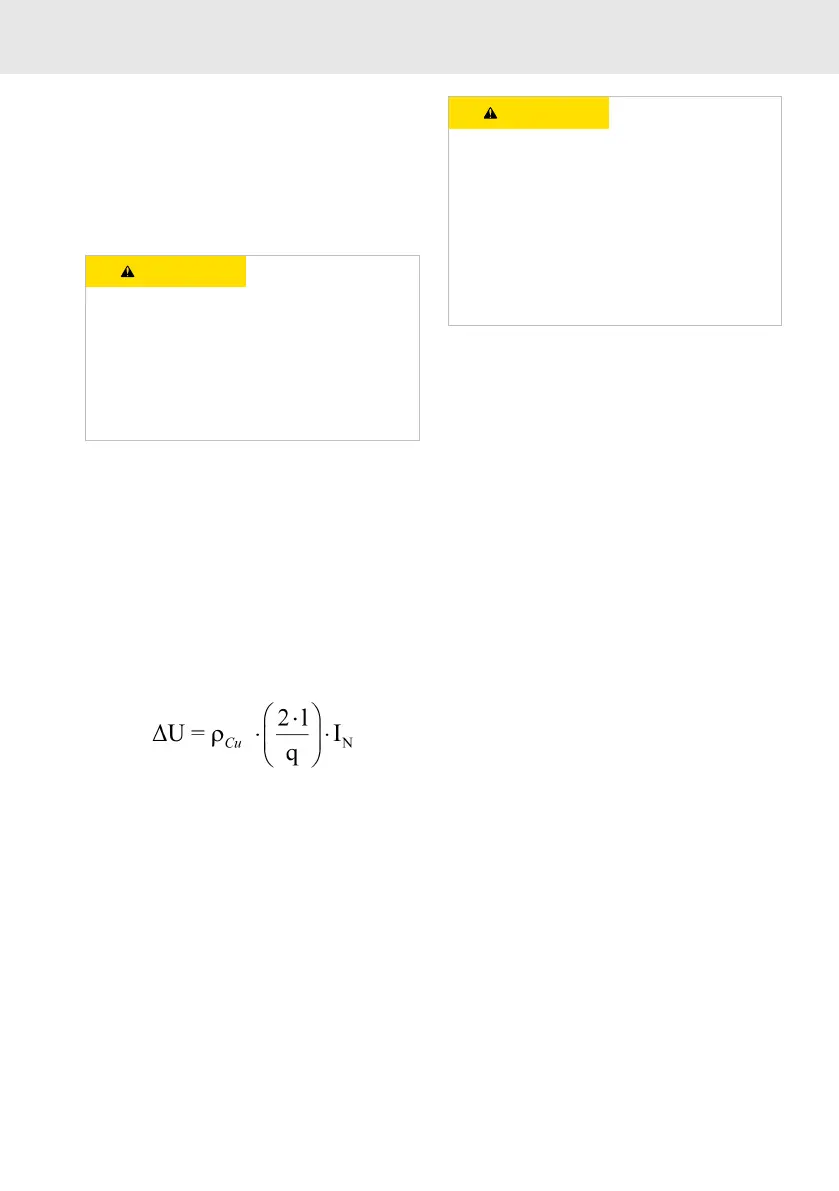
The voltage drop ΔU on the brake supply can
approximately be calculated for copper conduc-
tors using the following formula:
Fig. 1: Voltage drop of brake supply for Cu
(copper) conductor
ΔU
Voltage drop [V]
ρ
Cu
Specific resistance of copper [Ω*mm
2
/m]
l Cable length [m]
q Wire cross section [mm
2
]
I
N
Rated current [A]
CAUTION
Malfunction in case of exceeded tolerance of the
rated voltage (switching voltage)
For safe switching of the holding brake, a rated
voltage of 24 V DC ±10% is required at the
motor.
Ensure correct dimensioning of the supply wires
(wire length and cross-section) for the holding
brake.
The control voltage can be reduced using the
energy saving function after safely releasing the
brake.
The holding brakes are intended for direct con-
nection to the ctrlX controllers. A protective cir-
cuit to switch inductive loads of holding brakes is
integrated in ctrlX controllers.