7.3.2 Single cable connection for MS2S with encoder (digital "I") and optional
brake
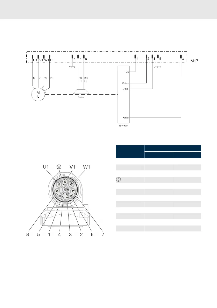
Circuit diagram
Fig. 5: Circuit diagram MS2S
7.3.3 M17 single cable connector,
rotatable (SpeedTec)
Fig. 6: Cable view of single cable connection M17
Designation Function
with brake without brake
U1 A1 A1
V1 A2 A2
W1 A3 A3
PE PE
1 +UB +UB
2 Data+ Data+
3 GND GND
4 Data- Data-
5 Shld_Enc Shld_Enc
6 Shld_BD Shld_BD
7 BD(+) n.c.
8 BD(-) n.c.
Adjustment range
The output direction of the single cable con-
nector M17 is adjustable. The device connectors
can be manually rotated of a plug connector has
been installed. Do not use any tools (e.g. pliers
or screwdrivers) to turn the device connector to
avoid damage.