16/48 Analog amplifier RA | About this product
BoschRexrothAG, RE95230-B/2021-12-01
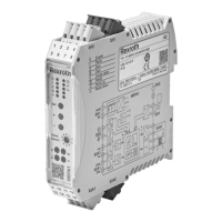
5�4 Assignment and function of the LEDs and setting potentiometer
1 2 3 4
5
6
8
7
10 11
9 12
Fig� 4: Assignment and function of the LEDs and setting potentiometer
1 Potentiometer maximum current I
max1
(PWM current channel 1)
2 Potentiometer minimum current I
min1
(PWM current channel 1)
3 Potentiometer downwards ramp t
down1
(PWM current channel 1)
4 Potentiometer upwards ramp t
up1
(PWM current channel 1)
5 Potentiometer maximum current I
max2
(PWM current channel 2)
6 Potentiometer minimum current I
min2
(PWM current channel 2)
7 Potentiometer downwards ramp t
down2
(PWM current channel 2)
8 Potentiometer upwards ramp t
up2
(PWM current channel 2)
9 PWM current channel 2 (I2 - yellow LED)
10 Power (operating display - green LED)
11 Error (error display - red LED)
12 PWM current channel 1 (I1 - yellow LED)
The brightness of LEDs I1 and I2 depends on the strength of the output current
and thus serves arough visual control.
The ramps control the time required by the output current to reach anew
value. The control range is between 100 ms and 10 s at maximum change from
I
min
to I
max
.
For the potentiometers, the following applies in general: Clockwise rotation means
an increase in the setting (longer ramp time or higher current).

 Loading...


