34/124 Bosch Rexroth AGSB356 | 3 609 929 B67/2008-11
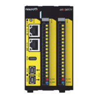
Fig. 7: X1N4 voltage selection terminals (SB356) with connection groups G1, G2, G3
The X1N4 interface partitions represent a
logical separation of the 3 possible mains
connection groups (G1 to G3).
A screwdriver with a 2 mm blade can be used
as a wiring tool.
}
.1
.2
.1
.2
.1
.2
.3
.4
1
.1
.2
.1
.2
.1
.2
.1
.2
.1
.2
.1
.2
.1
.2
234 567 8910
.1
.2
.1
.2
.1
.2
11 12 13
G1 G2 G3 G4
Terminal strips for mains connection Device connection
Table 2: Voltage selection terminals
Pin Signal Description/
function
Voltage/
current
1PE PE wire PE potential
G1
2L1
L1 mains
connection
380 V~ -
415 V~/4.6 A
3L2
L2 mains
connection
380 V~ -
415 V~/4.6 A
4L3
L3 mains
connection
380 V~ -
415 V~/4.6 A
G2
5L1
L1 mains
connection
440 V~-
480 V~/3.9 A
6L2
L2 mains
connection
440 V~-
480 V~/3.9 A
7L3
L3 mains
connection
440 V~-
480 V~/3.9 A
G3
8L1
L1 mains
connection
500 V~/3.5 A
9L2
L2 mains
connection
500 V~/3.5 A
10 L3
L3 mains
connection
500 V~/3.5 A
G4
11 L1
L1 device
connection
230 V~/7.5 A
12 L2
L2 device
connection
230 V~/7.5 A
12 L3
L3 device
connection
230 V~/7.5 A
WARNING!
Only the voltage selection terminals for the
G1, G2 and G3 groups are intended for
assignment of the mains connection. The
device connection may not be assigned.
WARNING!
Only the connections of one group may be
used. Do not use more than one group at
the same time.
Failure to adhere to this may lead to the
destruction of the device.
WARNING!
As the pin assignment (Table 2) indicates,
the mains must always be connected to the
upper terminal strip.
The lower terminal strip must remain fully
wired.

 Loading...