Ø 8
2
100
165
182
89
7
3HE (128,4)
VSPA1
4TE
(20)
w
I
Gw
M0
H2
t
t
X1
10
135
100
160
80
4 x Ø 4,5
164
104
10
Hydraulics Bosch Rexroth AG
RE 30111/09.05
VT-VSPA1-1 and VT-VSPA1K-1
11/12
Unit dimensions (nominal dimensions in mm)
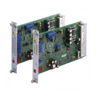
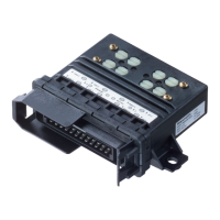
VT-VSPA1K-1
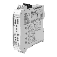
VT-VSPA1-1
Engineering / maintenance notes / supplementary information
– Before commissioning the amplifiers, make sure that the DIL switches on the printed-circuit board are set according to the
relevant application.
– The factory setting of the parameters is as follows (for the adjustment of parameters, see pages 8 to 10):
max. ramp time = 5 s, biasing current = 100 mA, max. output current = 800 mA, clock frequency = 200 Hz
– The amplifier card may only be installed when disconnected from the power supply!
– Do not use plugs with free-wheeling diodes or LED lamps for connecting the solenoids!
– Measurements on the card may only be taken with instruments R
i
> 100 kΩ !
– Measuring zero (M0) is raised by +9 V as against 0 V operating voltage and not electrically isolated, i.e. –9 V regulated voltage
0 V operating voltage. For this reason, do not connect measuring zero (M0) to 0 V operating voltage!
– Use relays with gold-plated contacts for passing on command values (small voltages, small currents)!
– Always shield command value cables; connect the shield to ground on the card side and leave the other end open. Connect the
card to ground at terminal 6 or 8. If no system ground is provided, connect 0 V operating voltage.
Recommendation: Also shield solenoid cables!
For solenoid cables of up to 50 m length, use cable type LiYCY 1.5 mm
2
. For greater lengths, please consult us!
– The distance to aerial lines, radio sources and radar equipment must be at least 1 m!
– Do not lay solenoid and signal cables near power cables!
– Due to the charging current of the smoothing capacitor on the card, fuses must feature slow-blowing characteristics!
Caution! When the differential input is used, both inputs must always be switched on or off simultaneously!
Note! Electrical signals (e.g. signal “ready for operation”) brought out via control electronics must not be used for
switching safety-relevant machine functions!
(See also European standard “Safety requirements for fluid power systems and components - hydraulics“,
EN 928.)
 Loading...


