Bosch Rexroth AG
Hydraulics
Zum Eisengießer 1
97816 Lohr am Main, Germany
Phone +49 (0) 93 52 / 18-0
Fax +49 (0) 93 52 / 18-23 58
documentation@boschrexroth.de
www.boschrexroth.de
© This document, as well as the data, specifications and other information
set forth in it, are the exclusive property of Bosch Rexroth AG. It may not be
reproduced or given to third parties without its consent.
The data specified above only serve to describe the product. No state-
ments concerning a certain condition or suitability for a certain application
can be derived from our information. The information given does not
release the user from the obligation of own judgment and verification. It
must be remembered that our products are subject to a natural process of
wear and aging.
12/12 Bosch Rexroth AG Hydraulics
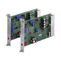
VT-VSPA1-1 and VT-VSPA1K-1
RE 30111/09.05
Troubleshooting
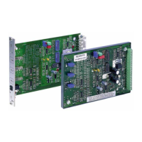
If the amplifier cards are not operable, follow the steps below
for troubleshooting:
1. Is the operating voltage applied?
Measurement of contacts 24(ac) against 18 (ac)
2. Fuse on the card defective?
3. Internal ±9 V operating voltage available on the card?
4. When the internal command value potentiometer is used,
is the jumper from 10(ac) to 12(ac) plugged?
5. Is the external potentiometer properly connected?
6. Is the differential input properly connected?
Check: Reference potential to 30(ac)
0 to +10 V to 28(ac)
7. Is the solenoid properly connected?
When the card is unplugged, a resistance of approx. 20 Ω
to 30 Ω or 5 Ω to 8 Ω, depending on the valve, must be
measurable between contacts 22ac and 20ac.
The additions to the contact designations are only valid for type
VT-VSPA1-1.
Note:
The output stage shuts down in the case of excessive temper-
atures (e.g. caused by overloading). This fault is signalled by
LED "H2" going out!
In the event of a cable break of the "4 to 20 mA" input, the sig-
nal "ready for operation" is reset and LED "H2" also goes out.
The following is valid from component series 11 onwards:
In the case of a short-circuit or cable break of the solenoid ca-
ble, the output “ready for operation” is switched and LED "H2"
flashes at a frequency of
0.5 to 2 Hz as soon as the command
value is > 2 %
at the same time.
 Loading...


