u
i
2,5 A T
2 x 220 µF
U/I
U
1
2
3
12
14
13
10
11
15
4
5
8
9
32ac
22ac
20ac
26a
14ac
24ac
18ac
16ac
14ac
6ac
8ac
10ac
30ac
28ac
12ac
+ 24 V
M0 (25 mA)
+ 9 V (25 mA)
0 V
– 9 V (25 mA)
S1.1...S1.3
S1.4
Gw
H2
&
DC
Zw (R130)
S2.5...S2.7
S1.7
S1.5
S1.6
16
S2.3 / S2.4
4ac
2c
2a
17
+ 24 V
26c
DC
Σ
t t
Σ
6
7
Σ
⬃
4/12 Bosch Rexroth AG Hydraulics
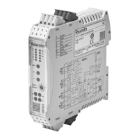
VT-VSPA1-1 and VT-VSPA1K-1
RE 30111/09.05
Block circuit diagram / pin assignment: VT-VSPA1-1
Command
value "w"
Ready for operation
24 V (50 mA)
Command value
2
+10 V
4 - 20 mA / 0 - 20 mA
GND ⊥
Command value 1
Act. current value
1 mV 1 mA
Note: Measuring zero (M0) is raised by 9 V as against 0V operating voltage!
Comm. value 0 to 6 V
Actual current value
"I"
I
Soll
S1.7 off on
I
max
1.6 A 0.8 A
f
–3dB
S2.3 S2.4
0 off off
2,5 Hz off on
4 Hz on off
f
clock
S2.5 S2.6 S2.7
100 Hz on on on
200 Hz off on on
300 Hz off off on
Comm. value 2
S1.1 S1.2 S1.3
0…10 V off off off
0…20 mA on on off
4…20 mA on on on
S1.4 on off
t
max
5 s 1 s
Char. curve 1
Char. curve 2
Ramp "up" OFF
Ramp "down"
OFF
1
Differential input
2; 5; 15
Summator
3
Max. command value attenuator
4
Ramp generator
6
Characteristic curve generator
1
7
Characteristic curve generator 2
8
Current regulator
9
Current output stage
10
Clock-pulse generator
11
Proportional solenoid of valve
12
Command value monitoring
13
Monitors
14
Power supply unit
16
Low-pass filter
17
Output “ready for operation“
H2
= Signal “ready for operation“
Gw
= Command value attenuation
t
= Ramp time adjustment
Zw
(R130)
=
Additional biasing current adjustment
(0 to 300 mA or 0 to 600 mA)

 Loading...


