36
Bosch Security Systems 09/07 BLCC500R FTR1.02
Copyright © 2007 E&OE
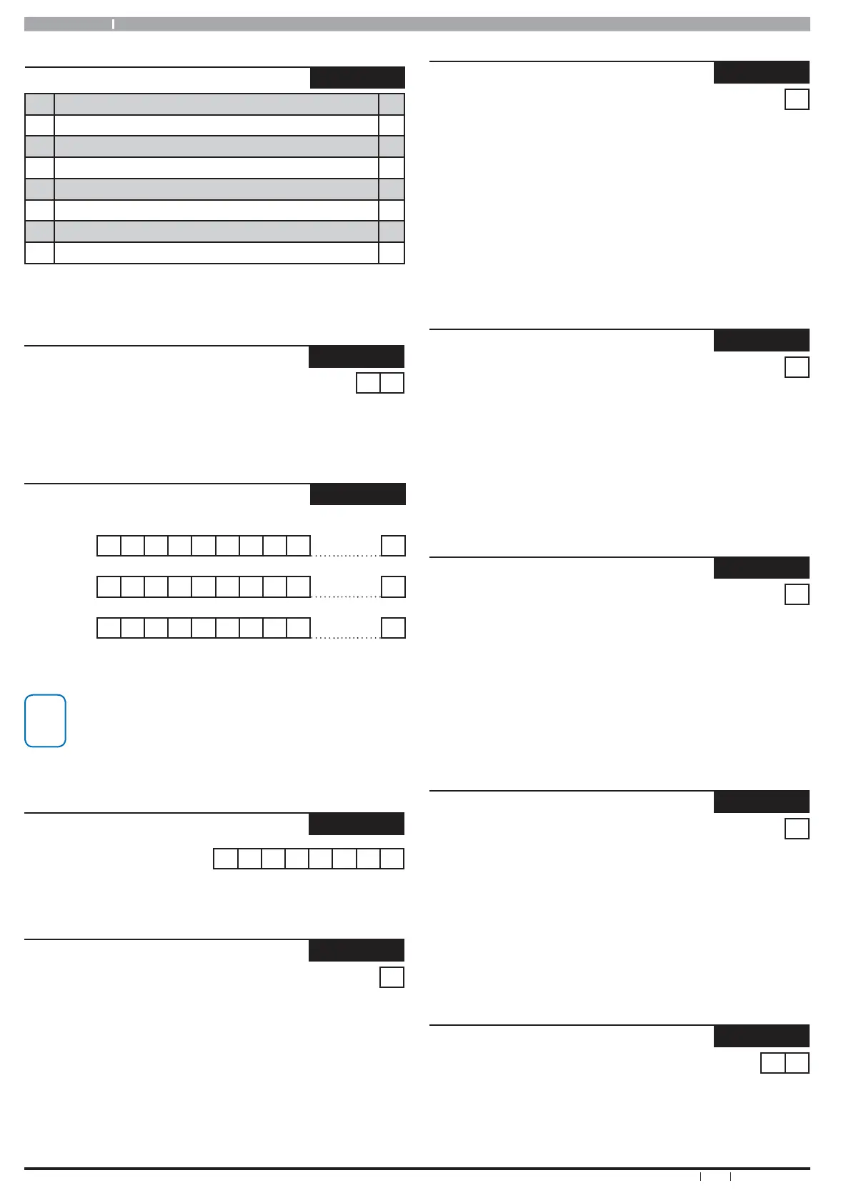
Comms > Remote Access >
DTMF Options
MENU 5-3-5
1 DTMF Arming Y
2 DTMF Disarming N
3 DTMF User Functions N
4 DTMF Quick Arm ([0] + [#]) Y
5 Reserved N
6 Reserved N
7 Reserved N
8 Reserved N
This location is a Bit option field. Press Keys [1] – [8] to turn ON and
OFF the required options. The option is selected or ON when the
coresponding zone indicator is on. Press [OK] To Save when finished.
Comms > Remote Access >
Voice Access Code
MENU 5-3-6
9 #
If a Voice Module is used enter the 2-digit access code used to access the
system. Enter [0] – [9] For Digits and Use [] and [] To Toggle Special
Characters.
Comms > Remote Access >
CLI Number
MENU 5-3-7
First
Number
1 Digits 32
Second
Number
1 Digits 32
Third
Number
1 Digits 32
Use [] and [] Keys To Scroll Cursor. Enter [0] – [9] For Telephone
Digits. Use [] and [] To Toggle Special Characters # and , (Pause)
Up to 3 Phone numbers can be entered for CLI
remote access detection. You must enter STD code
plus the compete number for this option to work.
Press [OK] after each telephone number is entered
to save and move to the next number.
Comms > Remote Access >
User RAS Security PIN
MENU 5-3-8
0 0 0 0 0 0 0 0
Use keys 0 - 9 To Program RAS Security PIN + [OK] To Save. This PIN
is used the authenticate during end user remote access connections.
Comms > Dialler Reporting >
TX Format Dest 1
MENU 5-4-0
0 = Disable
1
1 = Contact ID 7 = Domestic
2 = SIA 8 = Voice 13 = Reserved
3 = Serial STU 9 = SIA + 14 = Reserved
4 = GSM 10 = Reserved 15 = Reserved
5 = WEB MAIL 11 = Reserved
6 = SMS 12 = Reserved
Enter 0 – 15 Then Press [OK] To Program The Transmission Format The
Control Panel Will Use To Report To Destination 1.
Only 1 Option Can Be Programmed In This Location.
Comms > Dialler Reporting >
TX Format Dest 2
MENU 5-4-1
0 = Disable 1
1 = Contact ID 7 = Domestic
2 = SIA 8 = Voice 13 = Reserved
3 = Serial STU 9 = SIA + 14 = Reserved
4 = GSM 10 = Reserved 15 = Reserved
5 = WEB MAIL 11 = Reserved
6 = SMS 12 = Reserved
Enter 0 – 15 Then Press [OK] To Program The Transmission Format The
Control Panel Will Use To Report To Destination 2.
Only 1 Option Can Be Programmed In This Location.
Comms > Dialler Reporting
Test Route
MENU 5-4-2
0 = Report Events To Log Only
1
1 = Report Events To Destination 1 + Log
2 = Report Events To Destination 2 + Log
3 = Report Events To Destination 1 & Destination 2 + Log
4 = Report Events To Destination 2 If Destination 1 Fails + Log
Location 5-4-2 Sets The Report Route For Test Reports.
Enter 0 - 4 + [OK]. Only One Option Can Be Selected.
(*** System Wide Parameter ***)
Comms > Dialler Reporting
Status Route
MENU 5-4-3
0 = Report Events To Log Only
1
1 = Report Events To Destination 1 + Log
2 = Report Events To Destination 2 + Log
3 = Report Events To Destination 1 & Destination 2 + Log
4 = Report Events To Destination 2 If Destination 1 Fails + Log
Location 5-4-3 Sets The Report Route For System Status Reports.
Enter 0 - 4 + [OK]. Only One Option Can Be Selected.
(*** System Wide Parameter ***)
Comms > Dialler Reporting
Emergency Route
MENU 5-4-4
0 = Report Events To Log Only
1
1 = Report Events To Destination 1 + Log
2 = Report Events To Destination 2 + Log
3 = Report Events To Destination 1 & Destination 2 + Log
4 = Report Events To Destination 2 If Destination 1 Fails + Log
Location 5-4-4 Sets The Report Route For All Emergency Reports.
Enter 0 - 4 + [OK]. Only One Option Can Be Selected.
(*** System Wide Parameter ***)
Comms > Dialler Reporting >
Swinger Dialler
MENU 5-4-5
0 6
Enter 0 – 15 + [OK] To Program Number Of Times The Dialler Can
Report Before Lockout. (*** System Wide Parameter ***)
0 = Unlimited Attempts