6720866942 (2018/06) US SSB
16 | Installation
3” Flanged Gas Connection
10” PP Flue Venting
10” Air Intake
1”1/2 Condensate outlet
2” Relief valves outlet
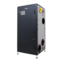
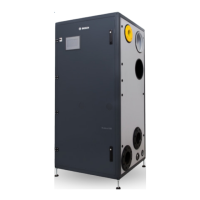
Fig. 13 SSB 1000 TL Connections
CAUTION: Before connecting the boiler to the heating
system, ush the heating system to remove sediment, ux,
dirt, and other foreign matter. The heat exchanger may be
damaged by sediment or corrosion.
CAUTION: Do not use cleaning uids that are not
compatible with the boiler materials, including acids (e.g.
hydrochloric acid and similar ones) at any concentration.
CAUTION: Introducing fresh water to the system increases
the oxygen presence and can cause corrosion of metallic
components. Immediately repair any drips or leaks in the
system to avoid constant introduction of air into the system.
CAUTION: Excessive uctuation in pressure changes in the
system can cause fatigue and stress on the heat exchanger.
This is detrimental to the integrity of the boiler and system
components, it is mandatory to maintain a constant
operating pressure.
4.4.1 Low water cutoff
A low water cut off (LWCO) is installed on each module of the boiler.
To check the functionality of LWCO go to the Module Test screen on the
Touchscreen (see section Operation) and then click on LWCO test. On
the screen will appear the error “Low Water Cutoff Error”. At this point
press the reset button. The error will turn off.
4.4.2 No Flow test procedure
To simulate a no water ow condition, the following steps should be
followed:
• Turn power off to boiler
• Disconnect module 1 pump power
• Turn power on to boiler
• Press “Test mode” button on module 1 screen
• Select “high power”
Module 1 will subsequently shut down as a result of no ow error.
Repeat the same process for each module of the boiler / cascade.
4.4.3 High limit safety switch
A high limit safety switch is installed on each module of the boiler.
To test the High limit sensor functionality, there are two options available:
A Electronic test (default):
to simulate a high limit lockout go to the Module Test screen on
the Touchscreen (see “6.3.8 Module Test Screen” pag. 37) and
then click on High limit test button. The system generates a high
limit lockout signal that shut the module down (and makes the reset
button available on the screen). Pressing the reset button the module
restarts;
B Physical test:
to trip the high limit sensor by increasing the water temperature up to
208°F, go to the Service display and enable the physical high limit test
Settings->Boiler Settings->Boiler Parameters->(183) High Limit Test
Then move to the Module Test screen on the Touchscreen (see “6.3.8
Module Test Screen” pag. 37) and click on High limit test button.
Follow the step by step procedure described below:
• Progressively close the return manual stop valve to reduce the ow
into the module under test;
• Check the module supply temperature on the screen;
• Reduce the ow until the control will display “Max. Thermostat Lock”
error and the module stops;
• At this point press the reset button to restart the module.
CAUTION: The Physical test is not recommended: forcing
the boiler to a low water ow condition may expose the
heat exchanger to potential overheating. The Manufacturer
declines any responsibility on damages derived from this
kind of test.
4.4.4 Pressure relief valve installation
ASME rated Pressure Relief Valves are factory installed in each module
of SSB boilers. The pressure rating for the relief valves is 75 PSI. The
relief valves are installed on each hot water supply pipe of the modules
as shown in Fig.8. The relief valves drain pipes are connected to the
manifold running at the bottom of the boiler. The manifold must be routed
to a nearby oor drain.
Relief valves should be manually operated at least once a year.
If a relief valve discharges periodically, this may be due to thermal
expansion in a closed water supply system.
Contact the water supplier or local plumbing inspector on how to correct
this situation.

 Loading...
