16 en | Product description VOT-320
DOC | V4.5 | 2010.09 Installation and Operating Manual Bosch Sicherheitssysteme GmbH
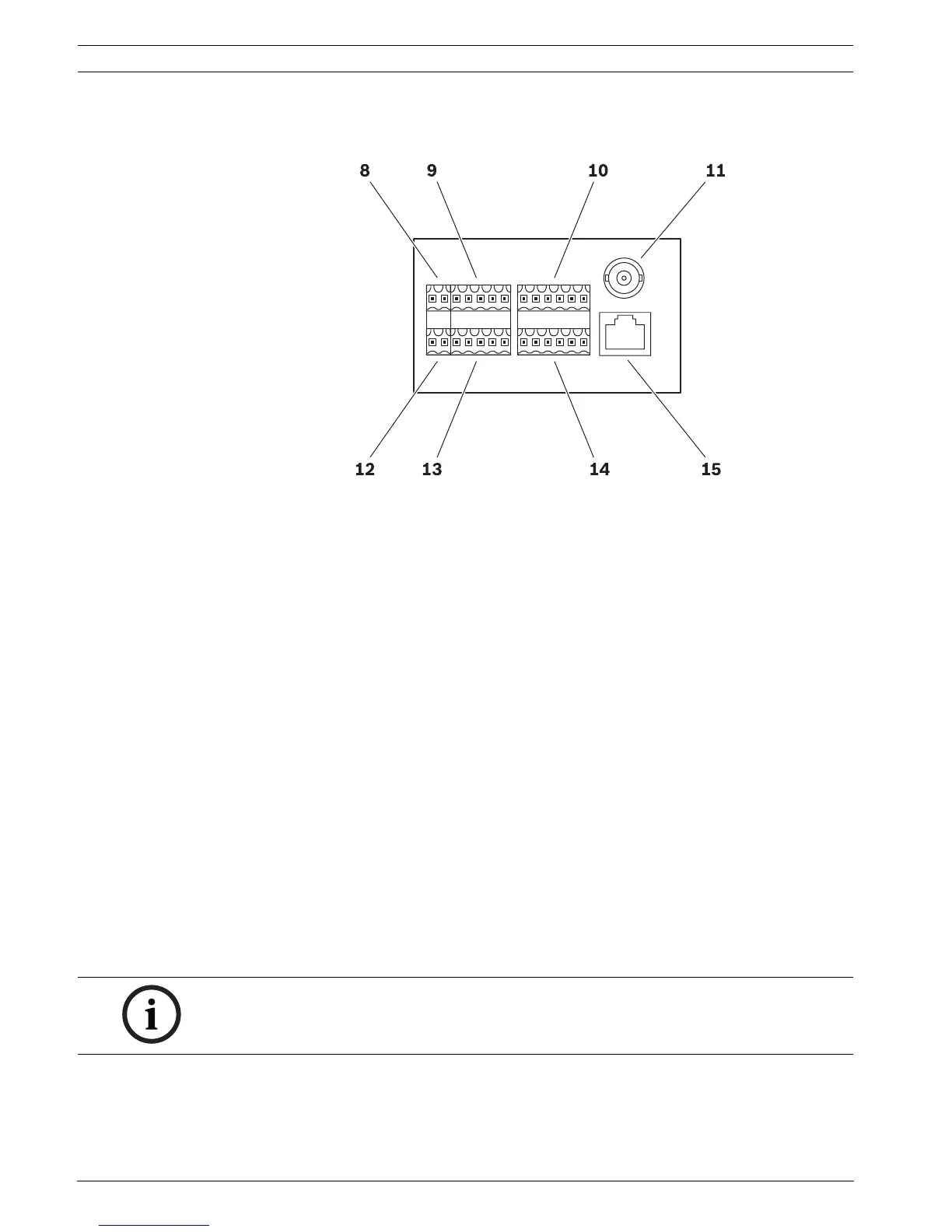
3.5 Connections on the camera module
8 Upper 2-pin terminal block
for power supply
9 Upper 5-pin terminal block
for pan/tilt connections
10 Upper 6-pin terminal block
for serial interface connections
11 Video output
BNC socket for connecting a service monitor during camera set-up
12 Lower 2-pin terminal block
for window defroster
13 Lower 5-pin terminal block
for pan/tilt connections
14 Lower 6-pin terminal block
for alarm inputs and relay outputs
15 RJ45 socket
for connecting to an Ethernet LAN (local network), 10/100 MBit Base-T
NOTICE!
For terminal block assignment, see Section 8.8 Terminal blocks, page 99.