12 MAINTENANCE & SERVICING 12.2 Rear Shock
62
Removal of the Rear Shock - To remove the rear shock, use a 5mm Allen
key to undo the M8 Cap Head Bolt (A) from the Top-Tube Shock Mount
(1). Once the bolt has been removed the Shock (B) is released from the
front triangle. Next, Whyte recommend to remove the Shape-It Link (E)
from the Rocker Link (2) to make extraction easier. Using the 5mm Allen
Key, unscrew and remove the two M15 Pivot Bolt (H). You can now remove
the Rear Shock (B) and Shape-It Link (E) from the bike as pictured in the
diagram on the previous page. Take care to retain the Bearings (G) and
Shield Washer (F) during the shock extraction. Ensure these components
are kept safe and replaced in the original positions during re-assembly.
Once removed from the bike, to separate the Shock (B) from the Shape-
it Link (E), use the 5mm Allen key, undo and remove the M8 Cap Head
Bolt (A) from the Shape-it Link (E). Next, separate the Shock (B) from
the Shape-it Link (E). The shock Bushing will remain seated in the Shock
eyelet.
Re-Assembly of the Rear Shock onto the Frameset.
Take the rear Shock (B) and apply either SKF LG/AF 3E or Castrol
Optimol T anti-fret paste onto the side faces of the shock bushes, that
contact the Main Frame and Shape-It Link (E). Slide the front of the rear
Shock (B) into the Main Frame and Shape-It Link (E).
Align the head of the rear Shock (B) with the top-tube mount (1), then
using a 5mm Allen Key secure the shock screwing the M8 Cap Head Bolt
(A) through the Top-Tube Mount (1) and Shock (B) head. Next, make sure
that the holes in the Shape-It Link (E) line up with the rear end of the
Shock (B). Insert the M6 Socket Head Cap Screw (C). Using the 5mm AF
Allen tighten all bolts and wipe off any excess grease.
CAUTION! Ensure the Rear Shock (B) and the Shape-It Link
(E) are the correct way up, with any dials and levers facing
downwards and towards the front of the frameset, reference
exploded ‘Rear Swing Arm’ diagram.
INFO: Pay attention to the torque settings stated on the
external face of the Pivot Screw (H).
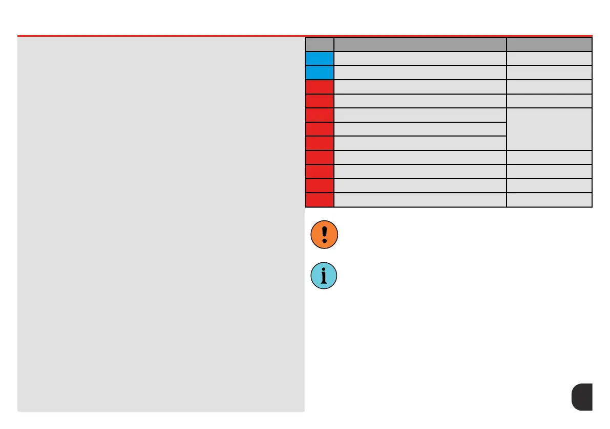
ITEM Part/Location Description Spare Part Kit Code
1 Top-Tube Shock Mount N/A
2 Rocker Link N/A
A M8x40 Cap Head Bolt WHYE-46
B Shock Model Specic
C M6 Socket Head Screw
EL-SHOCKEX60/64
D Bushing
E Shape-It Link (shock extender)
F 3mm Shield Washer (O.D 14mm I.D 10mm) WHYE-52
G 7mm Bearing (O.D 19mm I.D 10mm) 3800 Double Row
H Pivot Screw (M10 x 20mm) WHYE-52
AA Rocker Link Plug WHYE-40




 To Next Page