INSTALLING THE SOLAR PUMP STATION
6 720 643 603 (2011/11)
10
5 INSTALLING THE SOLAR PUMP STATION
5.1 LAYOUT OF THE INSTALLATION
SPACE
B To make it easier to connect the temperature sensors:
install the solar pump station (2) as close as possible
to the solar storage tank (1).
B Allow enough room for an expansion vessel (3) and
storage vessel (4).
Fig. 6 Recommended positioning
(measurements in mm)
1 Solar storage tank
2 Solar pump station
3 Expansion vessel
4 Storage vessel
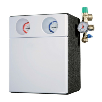
5.2 MOUNTING THE SOLAR PUMP
STATION
1-LINE SOLAR PUMP STATION
B Drill a hole (2) and mount the solar pump station
using the wall plug and screw supplied.
2-LINE SOLAR PUMP STATION
B Drill holes (1) 60 mm apart and mount the solar pump
station using the wall plugs and screws supplied.
Fig. 7 Mounting the station
1 Mounting for 2-line solar pump station
2 Mounting for 1-line solar pump station
5.3 ELECTRICAL CONNECTION
Electrical connections must be carried out by properly
authorised electricians and subject to locally applicable
regulations.
B Connect the cables for the pumps and temperature
sensors to the controller as directed by the
installation instructions for the controller.
CAUTION: Damage to the solar heating
station from pump buildup
B Make sure that the ventilation slots, at
the top and bottom of the thermal-
protective casing, are open.
7747006489.07.1.SD
CAUTION: Damage to pump
B Do not put the pump into operation until
the pipework has been filled. Otherwise
the pump can be damaged.
10 mm
8 mm
10 mm
7747006489.08-1.SD
2
60 mm
 Loading...