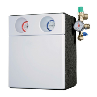
INSTALLING THE SOLAR PUMP STATION
6 720 643 603 (2011/11)
12
5.5.2 INSTALLING THE EXPANSION VESSEL
(AVAILABLE AS AN ACCESSORY)
B Install the expansion vessel with the relevant
mounting materials.
B Connect the expansion vessel (3) in the return line on
the solar heating station's safety assembly.
Fig. 10 Connecting the expansion vessel
1 Safety valve
2 Flexible stainless steel tube from connection set for the
expansion vessel (available as an accessory)
3 Expansion vessel
5.5.3 ADJUSTING THE INLET PRESSURE OF THE
EXPANSION VESSEL
B To make use of the maximum possible volume: set the
inlet pressure when the vessel is not under stress
(i.e. no fluid pressure).
B If the calculated inlet pressure is higher or lower than
the factory-set inlet pressure, correct the inlet
pressure accordingly.
5.6 CONNECTING PIPES AND BLOW-OFF
LINE TO THE SOLAR PUMP STATION
B Cut the pipes to a length which will allow them to be
pushed into the compression fitting (1) until they
bottom out.
B Route the blow-off line (2) from the safety valve so
that it can be seen to empty out into the storage
vessel (4) and secure it in place with a pipe clamp (3).
Fig. 11 Connection to solar pump station
1 Compression fitting
2 Blow-off line
3 Pipe clamp
4 Empty solar fluid container (storage vessel)
INSTALLING THE FILL AND DRAIN VALVE
B Install a fitting into the return pipe at the lowest point
in the solar heating system for draining the solar heat-
ing system (tee with fill & drain valve, Æ Fig. 12, (4)).
The inlet pressure of the expansion vessel is
given by the static system height plus
0.5 bar (1 metre difference in height equals
0.1 bar).
B Set a minimum pressure of 1.5 bar.
7747006489.16-1.SD
1
2
3
DANGER: Possible injuries and system
damage from incorrectly installed blow-off
line
B Make sure the blow-off line has the same
size as the cross-section of the safety
valve (maximum length = 2 m and
maximum of two bends).
7747006489.17-1.SD
1
3
1
1 41
2
 Loading...