INSTALLING THE SOLAR PUMP STATION
6 720 643 603 (2011/11)
11
5.4 INSTALLING THE SAFETY ASSEMBLY
B Install the safety assembly on the solar heating station
together with the gasket supplied (1).
Fig. 8 Installing the safety assembly of 2-line solar pump
station
1 Gasket (21x30x2)
5.5 CONNECTING THE EXPANSION
VESSEL AND PRE-COOLING VESSEL
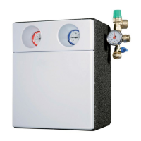
5.5.1 INSTALLING THE PRE-COOLING VESSEL
(AVAILABLE AS ACCESSORY)
A pre-cooling vessel is required:
• If the system is to be used to assist the central heating
system.
• If the system is purely for DHW heating: the solar
fraction is more than 60 %.
The pre-cooling vessel protects the expansion vessel
from excessively high temperatures.
CONNECTING THE PRE-COOLING VESSEL
If the pipeline to the expansion vessel needs to be laid
on a rising incline, an additional air vent must be
installed.
B To protect the safety valve from excessive
temperatures: connect the pre-cooling and expansion
vessels with a tee (¾ " threaded outer with flange
gasket) in the return line 20 to 30 cm above the solar
heating station.
B Secure pipes to and from the pre-cooling vessel with
pipe clamps (4). Mount the pre-cooling vessel
vertically.
B Connect the expansion vessel (5) to the pre-cooling
vessel by means of a copper pipe.
B Seal the connection on the safety valve with a ¾ " cap
(2) (to be provided by the customer).
Fig. 9 Installing the pre-cooling vessel
1 Flexible stainless steel tube from the connection set for the
expansion vessel (available as accessory)
2 Plug on the safety assembly connection
(provided by customer)
3 Pre-cooling vessel
4 Pipe clamp (provided by customer)
5 Expansion vessel
For 1-line solar pump station:
B Install the safety assembly on the left.
For 2-line solar pump station:
B Install the safety assembly on the right.
Do not insulate the pre-cooling vessel
(if fitted) and the expansion vessel, nor the
pipes connecting them to the safety
assembly.
5 litres 12 litres
Height 270 mm 270 mm
Diameter 160 mm 270 mm
Connection 2 x R ¾ " 2 x R ¾ "
Maximum operating pressure 10 bar 10 bar
Tab. 5 Pre-cooling vessel specifications
1
7747006489.13-1.SD
1
2
3
4
5
20-30 cm
7747006489.14-1.SD
 Loading...