COMMISSIONING
6 720 643 603 (2011/11)
18
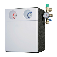
B Check the flow rate in the inspection window of the
flow limiter (Æ Fig. 20, (3)).
B To pre-set the flow rate: adjust the solar pump's
speed level switch (Æ Fig. 20, (4)) so that the
required flow rate is reached with as low a speed level
as possible.
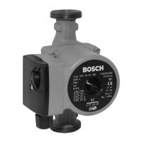
SPEED-CONTROLLED SOLAR PUMP
B Select the operating mode “Auto” on the controller.
The flow rate will be regulated by means of the solar
pump speed, based on current operating
requirements.
AFTER COMMISSIONING
The viscosity of the heat transfer fluid makes air bubbles
substantially more resilient than those in pure water.
B After several hours of solar pump operation, vent the
solar heating system via the de-airator in the solar
heating station and (if installed) the air vent on the
roof.
The values specified in Tab. 7 apply to
single-row collector arrays or multi-row
arrays connected in parallel. Collector
arrays connected in series must be set using
the total volumetric flow rate, which must
be calculated.
If the pre-set flow rate is not reached at the
pump's highest speed level:
B Check maximum permitted pipe lengths
and sizing (Æ section 4.1).
B If necessary, install a stronger pump.
Flow rate l/min (at 30 - 40 °C in return)
No. of collectors
(volumetric flow rate l/h) l/min
1 (50) 1
2 (100) 1.5 - 2
3 (150) 2.5 - 3
4 (200) 3 - 4
5 (250) 4 - 5
6 (300) 5 - 6
7 (350) 5.5 - 7
8 (400) 7 - 8
9 (450) 7.5 - 9
10 (500) 8 - 10
Tab. 8 Overview of flow rates
 Loading...