EasyManua.ls Logo

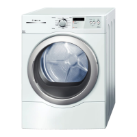
Bosch WTVC SERIES User Manual

Bosch WTVC SERIES
33 pages
To Next Page IconTo Next Page
Page #1 background imageLoading...
Page #1 background image
W
W
W
T
T
T
V
V
V
C
C
C
G
G
G
A
A
A
S
S
S
D
D
D
R
R
R
Y
Y
Y
E
E
E
R
R
R
R
R
R
E
E
E
P
P
P
A
A
A
I
I
I
R
R
R
I
I
I
N
N
N
S
S
S
T
T
T
R
R
R
U
U
U
C
C
C
T
T
T
I
I
I
O
O
O
N
N
N
1 SAFETY ........................................................ 2
2 INSTALLATION............................................ 3
2.1 Basic installation ................................................................ 3
2.2 Exhaust vents...................................................................... 3
2.3 Feet (leveling legs).............................................................. 3
2.4 AQUASTOP
®
(aqua secure)................................................ 4
2.5 General installation warnings ............................................ 4
3 OPERATION................................................. 5
3.1 Controls ............................................................................... 5
4 COMPONENTS............................................. 6
4.1 WTVC Gas Dryer Components .......................................... 6
4.2 Operation ........................................................................... 14
5 REPAIR....................................................... 15
5.1 Disassembly / Reassembly .............................................. 15
5.2 Kit Installation ................................................................... 25
5.3 Diagnosing (troubleshooting).......................................... 26
5.4 Dryer noise ........................................................................ 27
5.5 Customer diagnosing ....................................................... 27
5.6 Maintenance ...................................................................... 28
6 FAULT DIAGNOSTICS............................... 29
6.1 Overheating fault codes ................................................... 32
7 TECHNICAL SPECIFICATIONS ................ 33
7.1 Dryer ratings ..................................................................... 33
702_58300000143767_ara_en_a Page 1 of 33
Questions and Answers:

Bosch WTVC SERIES Specifications

General IconGeneral
BrandBosch
ModelWTVC SERIES
CategoryDryer
LanguageEnglish

Summary

SAFETY

INSTALLATION

Basic installation

Dryers shall be installed according to national and local codes.

Exhaust vents

Vent is factory installed to the rear of dryers. Rear factory vent can be changed to the bottom or right side using kits.

Feet (leveling legs)

Using a level front to back and side to side, adjust feet until dryer is level.

AQUASTOP® (aqua secure)

AQUASTOP® water inlet hoses prevent water from leaking. They connect like standard hoses with no special installation needed.

General installation warnings

Notices regarding appliance mounting, stacking, and handling precautions.

OPERATION

Controls

Overview of the dryer's control panel, including program selection and buttons.

COMPONENTS

WTVC Gas Dryer Components

Lists basic components like control module, gas burner, igniter, motor, sensors, and switches.

Drive motor

Details the specifications and function of the dryer's drive motor.

Gas valve

Describes the gas valve, including its regulator and jet for natural gas or LP.

Burner

Explains the burner's function and its relation to the gas valve and igniter.

Gas leak testing (using soapy water)

Step-by-step procedure for checking gas connections for leaks.

Flame sensor

Explains the role of the flame sensor in detecting flame out and reigniting flames.

Igniter

Describes how igniters glow to ignite gas flames and the need for careful handling.

Lint screen sensors

Locates lint screen sensors and their function in temperature regulation and safety.

Broken belt switch

Explains the function of the broken belt switch and how to reset it.

Air exhaust duct

Describes the air exhaust duct's connection to the fan and venting options.

Fascia (control) panel

Details the fascia panel, including the integrated knob and separate buttons.

Moisture sensor

Explains the moisture sensor's location and how it detects clothes dryness.

Door switch

Describes the door switch's function in controlling the light and dryer operation.

Fan wheel replacement

Warns against interchanging fan wheels between WTVC and WTMC models due to software matching.

Mist care (on selected dryers)

Explains the mist care function, which sprays water to refresh clothes and relax wrinkles.

AQUASTOP® (aqua secure) inlet hoses

Details the AQUASTOP® hose features, leak indicators, and usage with washers.

Round button assembly

Advises careful handling of round button assemblies due to delicate plastic rods.

Door glass cover

States that door assemblies are not available but components are disassemblable.

Front felt drum seal

Explains the replacement of the self-adhesive Teflon coated felt front seal.

Empty drum detection

Describes how dryers shut down if no moisture is detected after 11 minutes.

Wrinkle Block/Finished light

Explains that a damaged internal switch requires control module replacement if this light is on with the display off.

Serial # label

Identifies the location of the serial number and model label on the front panel.

Gas burner operation

Explains the electrical circuit for gas burner operation, including igniter and coils.

AQUASTOP® (aqua secure) hose operation

Details the operation of the AQUASTOP® hose, including leak detection and shut-off mechanisms.

REPAIR

Top panel (worktop)

Procedure for removing and reinstalling the top panel using Torx screws.

Fascia (control) panel

Instructions for removing the fascia panel held by plastic latches.

Control module

Steps for removing the control module from the fascia panel by releasing plastic latches.

Button caps (round / rectangular)

Advice on fitting button caps loosely and preventing them from falling out during reassembly.

Round button assembly

Guidance on carefully removing round button assemblies as a group.

Bottom front panel ("toe kick")

Instructions for removing the bottom front panel to access the maintenance cover.

Door removal

Steps for removing the dryer door, including hinge cover and latch cover screws.

Door disassembly

Procedures for disassembling the door, including removing the inner frame and glass.

Reversing door hinge

Instructions for reversing the door hinge from right to left position without needing parts.

Rear panel

Instructions for removing the rear panel for access to parts and power connection.

Drum and drum cover (with drum bearing)

Steps for removing the rear panel, belt, drum cover, and drum.

Gas valve and burner

Instructions for removing the gas valve and burner assembly, including gas pipe and wiring.

Motor, belt tensioner and broken belt switch

Describes the location and removal of the motor, belt tensioner, and broken belt switch.

Front panel

Steps for removing the front panel, including fascia, door, lint screen, and toe kick.

Front bearing shield

Procedures for removing the front bearing shield, including components like NTC, Hi-Limit, and lamp.

Moisture sensor

Instructions on accessing and removing the moisture sensor from the front bearing shield.

Fan

Details on removing the fan, noting the left-handed thread on the motor shaft.

Serial # (E-Nr) label

Identifies the location of the serial number and model label on the front panel.

Kit Installation

LP valve conversion kit

General guidelines for installing an LP valve conversion kit.

Diagnosing (troubleshooting)

Dryer noise

Customer diagnosing

Maintenance

Cleaning lint filter

Instructions for cleaning the lint filter and troubleshooting related error codes.

FAULT DIAGNOSTICS

Selecting the test program

Guide on activating test programs and navigating the diagnostic menu.

Fault display

Explains how fault codes are displayed, including error numbers and LED indicators.

Consumer test

Details the consumer test procedure, including motor and heating sequences.

Indicator Test (LEDs and LCD)

Procedure for testing all LEDs and LCD segments for functionality.

Operating Elements

Tests for buttons, options, and menu elements to check their illumination and function.

Demo program

Simulates a program sequence to test status LEDs and display.

Changeover 10A/16A (208V/240V) operation

Describes a test for voltage changeover, noting it may not have effects in EU.

Automatic end-of-line program

Explains the automatic test program used for quality control during production.

Overheating fault codes

Lists and explains overheating error codes (E:11, E:12, E:15) and their causes.

TECHNICAL SPECIFICATIONS

Dryer ratings

Provides electrical and gas specifications for WTVC gas dryers.

Drive motor ratings

Specifies electrical ratings for the dryer's drive motor.

Bulb ratings

Lists the voltage, wattage, and type for the dryer's indicator bulbs.

Drum volume

States the drum volume in cubic feet using U.S. DOE and IEC ratings.

Energy factor

Specifies the minimum energy factor requirement for the dryer.

Duct length (max.)

Indicates the maximum recommended length for rigid metal ducting.

Gas igniter ratings

Provides information on the glow temperature and resistance of gas igniters.

Flame sensor ratings

Specifies the reaction time of flame sensors to flame out conditions.

Air flow

Presents a graph showing volume flow rate versus exhaust duct length.

Related product manuals