7
DISASSEMBLY/ASSEMBLY PROCEDURES
5.2 Locate and remove the eight screws
holding the front panel to the chassis. Four
of the screws are located just inside the
two handles and the other four are the
larger screws on the front panel.
5.3 Using the handles pull the front panel
away from the chassis enough to access
the gain controls and LED PCB.
6. Front Panel Replacement
6.1 Slide the front panel into place. Be
careful not to pinch the wiring harness at
the bottom of the front panel between it
and the chassis.
6.2 Align the holes in the front panel with
the chassis, place the screws into their
location by hand and then tighten with a
screwdriver.
Note: While tightening the screws lift up
on the top lip of the panel to provide
enough room to slide the top cover under
the lip.
7. LED PCB Removal
7.1 Perform procedure 5.
7.2 Remove the two screws that secure
the PCB to the front panel.
7.3 Unsolder the wires at the LED PCB,
make a note of the wiring configuration,
and remove the board from the unit.
8. LED PCB Replacement
8.1 Place the LED PCB into place on the
front panel.
8.2 Secure the PCB to the front panel.
8.3 Resolder the wires to the LED PCB.
Note: Refer to Figure 1 for the following
procedures.
1. Top Cover Removal
1.1 Remove the four screws that secure
the top cover to the unit.
1.2 Slide the top cover towards the back of
the unit and lift it off.
2. Top Cover Replacement
2.1 Place the top cover on to the unit and
slide it under the front panel lip.
2.2 Secure the top cover to the unit.
3. Amplifier PCB Removal
3.1 Perform procedure 1.
3.2 Disconnect the wire harness, input
cable, and the two wires going to the
thermal cutout.
3.3 Remove the six screws (2B) located on
the side of the unit between the heat sink
fins (see Figure 2).
3.4 Carefully pry the PCB inward towards
the power transformer (the PCB is stuck to
the chassis by the heat sinking compound)
and lift the board out of the unit.
4. Amplifier PCB Replacement
4.1 Slide the PCB into place. Be sure there
is sufficient heat sinking compound on the
PCB's heat sink.
4.2 Align the six screws that secure the
PCB into place and secure the PCB to the
chassis.
4.3 Connect the wire harness, thermal
cutout wires, and the input cable to the
PCB.
5. Front Panel Removal
5.1 Perform procedure 1.
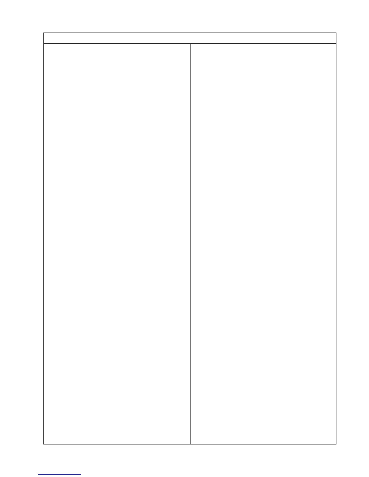
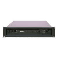
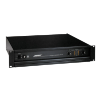
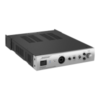
1800 Power Amplifier