EasyManua.ls Logo

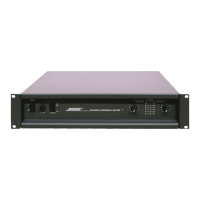
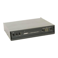
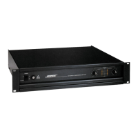
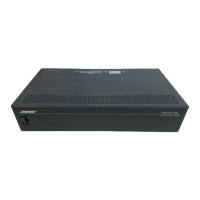
Bose 1800

Bose 1800
32 pages
To Next Page IconTo Next Page
Loading...
Bose
®
Model 1801/1800
Power Amplifier
Supplement
Part Number 192527-S1
©
2001 Bose Corporation
10/2001
SUPPLEMENT
Q4, part number 102428 and Q5, part number 102429 are no longer available with the lead length
needed for soldering to the PCB. Use the part numbers listed below when ordering these transis-
tors. Make a note in your Model 1801/1800 power amplifier service manual, part number 192527.
Reference
Designator
Description Part
Number
Note
Q4 SIM, 2N2219 102428-1K 1
Q5 SIM, 2N5415 102429-1K 2
NOTE: The part numbers listed are kits. They include the following parts:
1. Q4 kit: 1 102428 transistor
3 264371 extension pins
1 192527-S1 supplement.
2. Q5 kit: 1 102429 transistor
3 264371 extension pins
1 192527-S1 supplement.
Question and Answer IconNeed help?

Do you have a question about the Bose 1800 and is the answer not in the manual?

Bose 1800 Specifications

General IconGeneral
BrandBose
Model1800
CategoryAmplifier
LanguageEnglish

Summary

Specifications

Mechanical Specifications

Covers physical dimensions and weight of the amplifiers.

Power Requirements

Details voltage, frequency, and power consumption.

Amplifier Performance Metrics

Summarizes output power, distortion, frequency response, and S/N ratio.

Safety Information and Device Handling

General Safety Precautions

Describes how safety-critical parts are identified in the manual.

Electrical Safety Tests

Outlines leakage current and insulation resistance testing procedures.

ESDS Device Handling

Provides guidelines for safe handling of Electrostatic Discharge Sensitive devices.

1801 Amplifier Disassembly and Assembly

1801 Top Cover Procedures

Covers removal and replacement of the amplifier's top cover.

1801 Amplifier PCB Procedures

Details steps for removing and replacing the amplifier's main circuit board.

1801 Front Panel Procedures

Explains how to remove and reinstall the front panel assembly.

1801 Front Chassis Assembly Procedures

Covers removal and replacement of the front chassis.

1801 LED PCB and Meter Assembly Procedures

Details steps for accessing and replacing LED PCB and meter components.

1801 Front Panel Controls and Lamp Procedures

Guides on replacing front panel controls and lamps.

1800 Amplifier Disassembly and Assembly

1800 Top Cover and PCB Procedures

Covers top cover removal/replacement and amplifier PCB procedures for the 1800 model.

1800 Front Panel and LED PCB Procedures

Details front panel and LED PCB removal/replacement for the 1800 model.

1800 Control and Panel Procedures

Covers gain control, power switch, and rear panel procedures for the 1800 amplifier.

Test Procedures

Bias Adjustment Procedure

Explains how to set the bias current for the amplifier.

Frequency Response and DC Offset Testing

Details procedures for checking frequency response and DC offset.

Power Output and Distortion Testing

Outlines methods to measure power output and harmonic distortion.

Thermal Cutoff Procedure

Describes how to test the unit's thermal cutoff mechanism.

Part List Information

Part List Notes

Provides important notes and usage guidelines for the part list.

Main Component Listings

Contains comprehensive lists of parts for the amplifier models.

Component Breakdowns

Lists specific parts like capacitors, diodes, and transistors.

Troubleshooting Guide

DC Offset and High Current Troubleshooting

Addresses issues related to DC offset and excessive current.

Oscillation and Noise Troubleshooting

Guides on resolving oscillation and excessive noise problems.

Bias, Frequency Response, and Distortion Issues

Covers troubleshooting for bias, frequency response, and distortion problems.

Voltage Conversion Instructions

Voltage Conversion Steps

Provides detailed instructions for converting the amplifier's voltage.

Service Bulletins

PCB Interchangeability Bulletin

Discusses the interchangeability of amplifier PCBs and related changes.

Resistor Failure Bulletin

Details findings and modifications related to resistor failures.

Thermal Improvement Bulletin

Outlines methods to improve the amplifier's thermal stability.

Output Transistors Bulletin

Addresses changes and compatibility of output transistors.
Related product manuals