12
English
4.0 Operation
4.2 Rear panel (cont.)
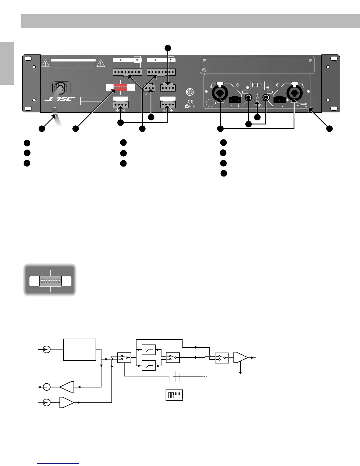
5. Speaker outputs
Barrier block speaker outputs on each channel accommodate independent connections for
4Ω, 8Ω, 25V, 35V, 50V, 70V, and 100V. The COM tap is the negative connection (–) and the
positive wire (+) connects to the desired load.
6. Effects loop
Independent serial effects (FX) Loops per channel allow you to add additional processing.
The FX Loop is unbalanced and can accommodate levels up to +20dBu.
7. Dip switches
Each channel has dip switches for Clip Limiter, High-Pass Filter and FX Loop.
Figure 5
Signal Path
OUT FX
CLIP OFF
HP OFF
80 Hz
INFX
CLIP ON
HP ON
120 Hz
Figure 4
Dip Switches
CH 2 CH 1
OFF
80 Hz
OFF
OUT
ON CLIP
120 Hz
ON HP
IN FX
OFF
80 Hz
OFF
OUT
ON CLIP
120 Hz
ON HP
IN FX
J20018292
SEND
RECV
SEND RECV
120VAC, 4.6A max.
60 Hz
600W
This device complies with part 15 of the FCC rules. Operation is subject to the following
conditions: (1) This device may not cause harmful interference and (2) this device must
accept any interference received, including interference which may cause undesired operation.
Complies with Canadian ICES-003 Class A specifications.
PN# 1234567
SEQUENCE REMOTE LEVEL
WARNING
RISK OF HAZARDOUS
ENERGY! MAKE PROPER
SPEAKER CONNECTIONS.
SEE OPERATING
MANUAL BEFORE USING.
AVERTISSEMENT
ENERGIE ELECTRIQUE
DANGEREU SE. VOIR
LANOTICE
DE FONCTIONNEMENT.
++
COM CH2 CH1 +5V
Com
4
8
25V
35V
50V
70V
100V
Com
4
8
25V
35V
50V
70V
100V
For bridged operation.
Consult user manual.
Use Class 2 Wiring
FX CH 1
CH 2 CH 1
FX CH 2
CH 2 CH 1
D.O.M.:
SERIAL No.:
BOSE CORPORATION
FRAMINGHAM, MA 01701-9168 U.S.A.
MADE IN U.S.A. OF DOMESTIC AND FOREIGN COMPONENTS.
CAUTION AVIS
RISK OF ELECTRICAL SHOCK
DO NOT OPEN COVER,
AUTHORIZED PERSONNEL
ONLY.
RISQUE DE CHOC ELECTRIQUE
NE PAS OUVRIR CE CARTER,
RESERVE AU PERSONNEL
AUTORISE.
WARNING
TO REDUCE THE RISK OF FIRE OR ELECTRICAL SHOCK DO NOT
EXPOSE THIS EQUIPMENT TO RAIN OR MOISTURE
SND RCV
®
OFF
80 Hz
OFF
OUT
ON CLIP
120 Hz
ON HP
IN FX
OFF
80 Hz
OFF
OUT
ON CLIP
120 Hz
ON HP
IN FX
+
INPUT IMPEDANCE 25K OHMS EACH LEG TO GROUND (TOTAL 50K OHMS BALANCED)
SEQUENCE
EQUALIZATION
SEND RECEIVE
12
3
ON
CH2
CH1
INPUT CH 2 INPUT CH 1
CH2 EQ. OUT
CH1
12
3
12
3
PUSH PUSH
++
Model 2150
2
4
5
6
1
9
7
8
3
10
1
Standard Input Module
2
Input Connectors
3
EQ Out Connectors
4
Equalizer Present LEDs
5
Speaker Outputs
6
Effects Loop
7
Dip Switches
8
AC Power Sequence Connector
9
Remote Level Control
10
IEC Power Cord
Signal
Effects
Send
Always
Hot!
Input Module
Electronic Switch
120H HPF
80 Hz HPF
Electronic Switch
Electronic Switch VCA Section
Signal to Amp
Output Stage
Master Level, Remote Level
Control Voltage Input
Configuration Dip Switch
Effects Receive
AM264080_00_V.pdf • June 21, 2002

 Loading...