8
English
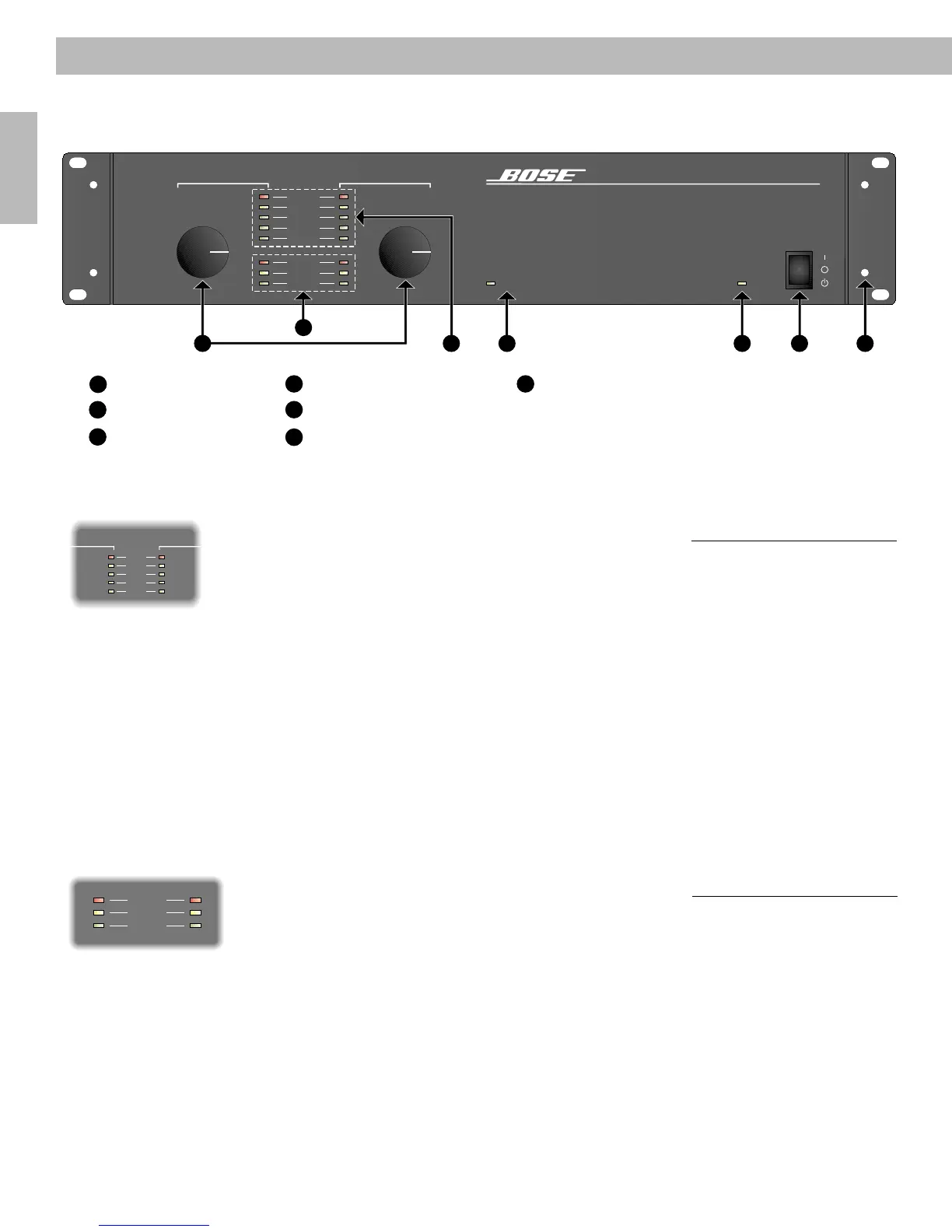
4.1 Front Panel (Cont.)
2. Level indicators
The level indicators (see Figure 2) for each channel reflect the gain of each output stage. The
following LEDs light up when the signal reaches each respective threshold:
• CLIP – red light indicates the signal is clipping (0dB)
• -6dB – yellow light indicates the signal is at -6dB below clip
• -12dB – green light indicates the signal is at -12dB below clip
• -20dB – green light indicates the signal is at -20dB below clip
• SIGNAL – green light indicates the signal is at -40dB below clip
It is common to operate the amplifier so that the CLIP (red) LED illuminates at the loudest
point. If the CLIP LED remains on for an extended length of time or clipping is audible, then
the level should be reduced on the channel(s).
3. Status indicators
Status indicators are visible for the following (See Figure 3):
THERMAL – A red light indicates when the amplifier temperature has exceeded its working
limits. When the THERMAL LED illuminates, both channels of the amplifier will become
muted. The amplifier will shut down and reset itself when conditions return to a safe operat-
ing temperature.
4.0 Operation
Ready
Protect
Thermal
Ready
Protect
Thermal
Clip
-12dB
-20dB
Signal
-6dB
Clip
-12dB
-20dB
Signal
-6dB
Ch 1 Ch 2
Figure 3
Status indicators
Figure 2
Level indicators
Clip
-12dB
-20dB
Ready
Signal
Protect
Thermal
-6dB
Clip
-12dB
-20dB
Ready
Signal
Protect
Thermal
-6dB
Ch 1 Ch 2
M 2150
Commercial Power Amplifier
Power
On
Off
Standby
Network
0dB
°
0dB
°
2
3
4
5
6
1
7
1
Level Controls
2
Status Indicators
3
Level Indicators
4
Network Activity Indicator
5
Standby Indicator
6
Power Switch
7
Removable Rack Ears
AM264080_00_V.pdf • June 21, 2002

 Loading...