65
Display PCB (continued)
Current overload or over-/ under-voltage events in the power amplifier trigger a protection control
cycle. During this timeout, Q433 [Signal Processor sheet2, G2] turns on, sinking current through
limiting resistor R460 lighting “Protect” LED D713 [Display PCB, D3] (J700p19 Signal Processor
Assy to P700p19 Display Assy). During thermal shutdown, comparator output U425p2 [Signal
Processor sheet2, D2] sinks current through limiting resistor R438 lighting “Thermal” LED D714
[Display PCB, D3] (J700p20 Signal Processor Assy to P700p20 Display Assy).
The “Network” LED indicates ACM-1 module control communications activity. “Network” LED
D700 [C1] lights when the ACM-1 sinks current through the LED from 15V (J8p2 ACM-1 to
J101p2 Signal Processor Assy, J700p11 Signal Processor Assy to P700p11 Display Assy).
ACM-1 Interface
Note: Refer to the Signal Processor PCB schematic sheets for the following information. The
designations inside the brackets “[ ]” indicate the grid coordinates for the component described.
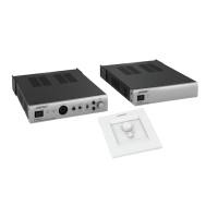
The ACM-1 interfaces to the amplifier Signal Processor assembly via input cable P100 [sheet 1,
A3/4] and output header J101 [sheet2, B4/5] (extended to the input module card cage by a cable
harness).
P100 provides digital and signal ground, ±15V power supplies and amplifier thermal monitor data
to the ACM-1. The ACM-1 sends sequence and signal inputs to the Signal Processor. Thermistor
R596 [sheet 1, B3] is attached to the heatsink. It tracks power amplifier heatsink temperature
from its location on the Signal Processor PCB assembly. R595 and thermistor R596 form a
temperature-dependent voltage divider with output fed through R593, R594 to ACM-1
(P100p7&8).
J101 feeds VS
POS
, CH1 and CH2 output current sense voltages, power ground, and amplifier
overload information to the ACM-1 for monitoring and control. Input from the ACM-1 drives the
“Network” LED and sets clip eliminator mode.
THEORY OF OPERATION
 Loading...
