56
This section describes the operation of the M2150 amplifier. Each functional block is considered
separately. Circuit function for Channel 1 is described in blocks where Channel 2 operation is
identical. Refer to schematic and block diagrams for additional information.
Overview
The Bose
®
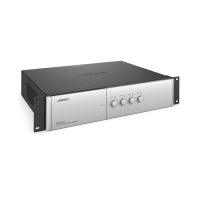
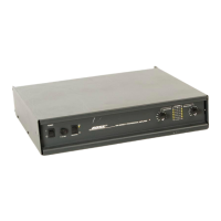
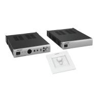
Model 2150 Commercial Power Amplifier is specially designed for commercial sound
applications. Its rugged construction allows it to sustain abuse with reliability. Accurate sound
and ample power make this amplifier ideal for critical listening applications.
The Model 2150 is rated at 150 Watts per channel into 4 Ohms, 8 Ohms, 25V, 35V, 50V, 70V or
100V. In bridged-mono operation, it is rated at 300 Watts.
Sophisticated protection circuits designed into the amplifier will protect it from excessive tem-
perature, continuous current limiting and shorted outputs.
The balanced inputs of the amplifier use a high quality, high common-mode rejection differential
amplifier for exceptional hum and noise rejection.
In addition, the Model 2150 amplifier is equipped with an input module to allow for separate
equalization of each channel (provided the correct equalization card is installed). Equalization
cards (EQ cards) are available for all Bose professional loudspeakers requiring active equaliza-
tion.
A sample setup might involve one Model 2150 amplifier driving two channels of 402
®
loudspeak-
ers in stereo mode. A second Model 2150 could be added to drive a 502
®
B module. Alternatively,
just one amplifier could be used to drive the 402 loudspeakers on one channel and the 502B
module on the other channel. Many configurations are possible using the four loudspeakers
above. This flexibility can be achieved by installing the EQ cards for the desired setup.
Optional ACM-1 amplifier control module
The Model 2150 amplifiers can also be used with the optional Bose ACM-1 amplifier control
module to allow monitoring and control of the amplifiers over a network. This network link makes
remote operation of signal level and power on/off functions possible. Using the graphical user
interface of the ACM-1 software module, settings like amplifier output, amplifier load, temperature
and clip levels can be checked routinely. The ACM-1 module is installed in the rear of the ampli-
fier in place of the standard input module and accepts all Bose equalization cards. Refer to the
ACM-1 installer's guide for complete installation instructions.
Power Supply
Note: Refer to the AC Input/Output PCB schematic sheet for the following information. The
designations inside the brackets “[ ]” indicate the schematic sheet and grid coordinates for the
component described.
AC mains current is supplied via the line cord and IEC inlet connector [AC Input/Output, A1]. The
mains filter [B1] isolates the amplifier from external noise and reduces noise conducted out of
the amplifier. Mains fuse F100 [D1] provides primary circuit protection.
THEORY OF OPERATION
 Loading...
