8
4.
Installation
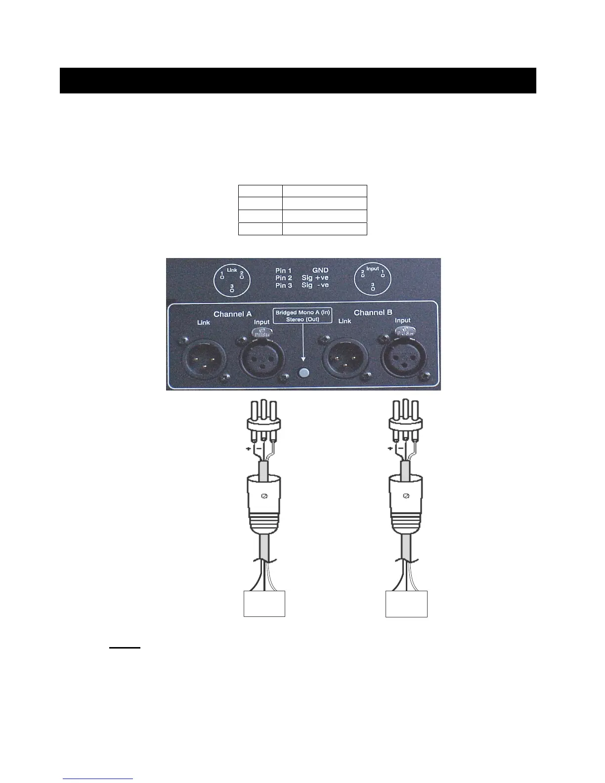
4.6 Input
s
The inputs are made via 3-pin XLR connectors, which are electronically balanced and
should be connected via a high grade twin core screened cable, as follows:
-
B
alanc
ed
operation
B
1500
shown only
GND
(Shield)
GND
(Shield)
PIN1
- Screen (see note)
PIN2
- Hot (signal +)
PIN3
- Cold (signal -)
-
+
GND
(Shield)
Balanced
Source
GND
+
-
-
+
GND
(Shield)
Balanced
Source
GND
+
-
Channel B
Channel A
NOTE
: This amplifier is wired to the latest industry recommendations. PIN1 is
connected directly to the chassis/mains earth. If ground loops (mains hum) are
encountered
, remove the screen connection from the other end of the cable and leave
it open circuit. If problems persist, consult your dealer/supplier. DO NOT TAMPER
WITH OR ALTER ANY GROUND (EARTH) CONNECTIONS INSIDE THE
AMPLIFIER.
Pin No.
Connection
1
Screen (ground)
2
Hot (signal +)
3
Cold (signal
-)