105
DISASSEMBLY PROCEDURE
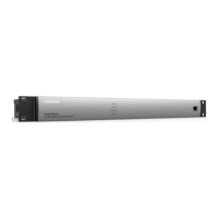
6. Acoustic Echo Cancellation (AEC)
PCB Removal
6.1 Perform procedure 1.
6.2 Remove the four screws that secure the AEC
PCB to the Main/DSP PCB.
6.3 Lift the AEC PCB straight up to disconnect it
from the Main/DSP PCB. There is a connector
mounted on the bottom of the AEC board that
plugs into the mating connector on the Main/DSP
PCB.
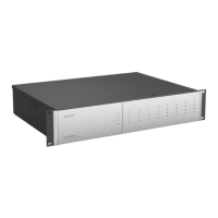
7. Dante
®
PCB Removal
7.1 Perform procedure 1.
7.2 Remove the one screw that secures the Dante
PCB to the Main/DSP PCB.
7.3 Move the two retaining clips located on the
sides of the Dante PCB’s connector outward. The
Dante PCB should move upward when released
from these clips.
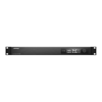
7.4 Slide the Dante PCB out of the connector at an
angle. Lift out the Dante PCB assembly.
Re-assembly Note: When re-installing the Dante
PCB, slide it into the connector at an angle and
press the back edge downward toward the Main/
DSP until it is retained by the connector clips.
Secure it in place with the one screw removed in
step 7.2.
 Loading...