37
DISASSEMBLY PROCEDURE
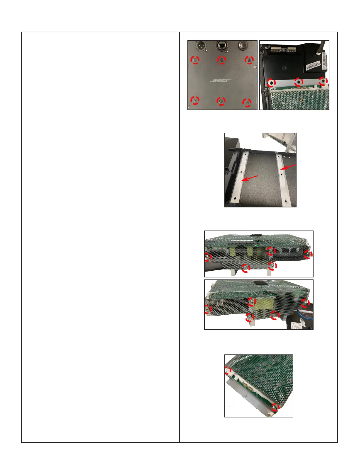
Figure 18. Shield Cover Screws Removal 2
4. Power-Amp Board Removal
4.1 Perform procedure 3.
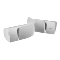
4.2 On the front of the I/O panel assy, remove
the 6 screws (left) and turn it over to remove
the 3 screws (right) securing the Power-Amp
board as indicated in Figure 15.
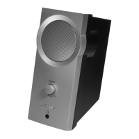
Re-assembly Note: the old Heat Sink thermal
grease must be removed with isopropyl alco-
hol and the new thermal grease, GAP FILLER,
THERMAL, part number 749859-0020 MUST
be used during board replacement. Failure to
use the correct thermal grease WILL cause
thermal failures. Part is listed at bottom of
page 14 on the Main Part List.Figure 16.
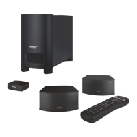
4.3 Remove the 12 screws that secure the
Shield cover of Power-Amp board as
indicated in Figure 17,18.
Note: When installing the Shield cover, RTV
need to be used to prevent buzz and vibration.
The location for RTV is same as the white
glue that is originally installed.
Figure 17. Shield Cover Screws Removal 1
Figure 15. Power-Amp Board Screws Removal
Figure 16. Heat Sink Thermal Grease

 Loading...