38
DISASSEMBLY PROCEDURE
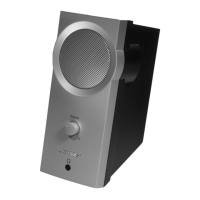
Figure 20. Fire Box & Main-I/O Board Screws
Removal
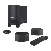
Figure 21. 4 Jacks and Jack Socket Nut
Removal
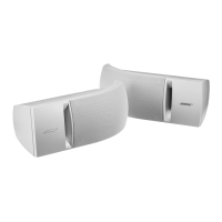
4.4 Use a spudger to separate the white glue
from the edge of PCB as indicated in Figure
19.
5. Main-I/O Board Removal
5.1 Perform step 4. On the Fire box, remove
the 5 screws that secure the Main-I/O board
as indicated in Figure 20 (left).
5.2 Remove the RTV with tweezers as the red
arrow indicated in Figure 20 (left).
Note: Be careful the Bluetooth antenna cable
when removing the RTV as it is fragile.
The new RTV need to be applied to the hole
when the re box is re-installed.
5.3 Lift the Fire box up and remove the 2
screws securing the Main-I/O board. Figure 20
(right).
5.4 Remove the green adhesive holding the
Bluetooth antenna cable and disconnect the
Bluetooth antenna connector as the red arrow
indicated in Figure 20 (right).
Note: The new green adhesive need to be
applied. Either hot melt or RTV is ne.
5.5 On the front of I/O panel assy, remove the
8 screws securing the 4 Jacks. Figure 21.
5.6 Use a nut driver or socket to turn ¼ turn to
remove the 1/4’ Jack socket nut out as the red
arrow indicated in Figure 21.
Re-assembly Note:
There are no Device ID concerns when re-
placing the main board. The Device ID is
assigned at the factory. Service replacement
Main-I/O PCBA’s use the PCBA serial num-
ber instead of the system serial number. As a
result, the system serial number will not show
up in the L1 Mix app.
Figure 19. White Glue Removal

 Loading...